Introduction to Device Communication in Embedded Systems
Introduction
Device communication in embedded systems is a key element to ensure the exchange of information between various electronic components. Whether it is for transmitting data between a microcontroller and a sensor, or for controlling peripherals such as screens or motors, communication must be reliable and adapted to the constraints of embedded systems (low power, limited space, etc.). We will first look at the different types of wired communication in embedded systems, then focus more specifically on three serial communication modes: UART, I2C, and SPI. Each of these protocols has unique characteristics that meet different needs.
Types of Communication in Embedded Systems
First, let’s review the basics of communication in embedded systems.
What is the Difference Between a Serial and a Parallel Protocol?
There are two types of communication protocols: parallel and serial.
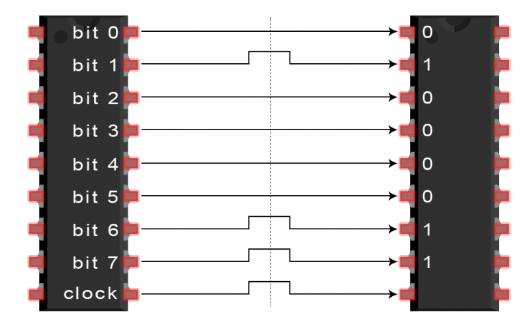
- Parallel communication protocols allow multiple bits to be sent simultaneously over multiple data lines, with each line carrying one bit. While this can offer faster data transmission compared to serial communication protocols, in rare cases, parallel communication can be slower due to issues like electromagnetic interference and signal degradation over longer distances. Additionally, parallel communication requires more wiring, making it more complex to implement. This protocol is commonly used in internal communication systems of processors (e.g., between the CPU and RAM).

-
Serial communication protocols send data bit by bit, meaning one data unit at a time. They use only one or two transmission lines, thus reducing the number of wires needed. Serial communication is often used in embedded systems where resources are limited, such as for connecting sensors, screens, or actuators. Common serial protocols include I2C, UART, SPI, or CAN.

We will focus here on serial communication protocols.
Synchronous or Asynchronous
Synchronous Communication
In synchronous communication, the communicating devices share a common clock signal. This clock signal synchronizes the sending and receiving of data, ensuring that bits are transmitted and received at the right time. Each bit sent by the transmitter is captured by the receiver based on the clock signal.
Asynchronous Communication
In asynchronous communication, there is no shared clock signal between the transmitter and the receiver. Devices synchronize only at the start of transmission using start and stop bits, indicating the beginning and end of a data packet. Each device uses its own internal clock.
Main Serial Communication Protocols
Here, we will look at the four most commonly used serial communication protocols.
UART
-
Operation
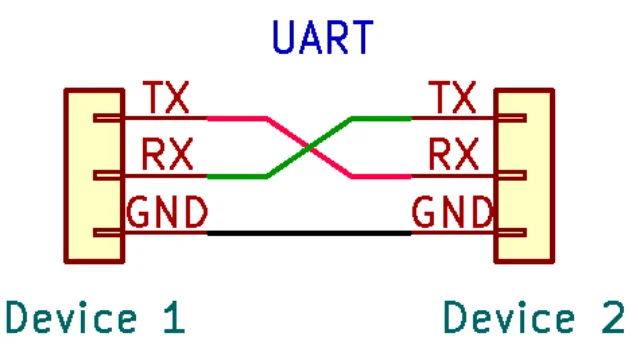
UART is a serial, asynchronous communication method. It is one of the simplest methods. Its role is to transmit data between two devices via two main lines:- TX (transmission)
- RX (reception)
Since UART is asynchronous, it does not require a common clock signal between devices, as each device has its own internal clock. UART uses a baud rate system, which represents the transmission speed (expressed in bits per second). Common baud rates are 9600, 19200, 115200. Both devices must have the same baud rate to communicate effectively. If the baud rates are not properly synchronized, transmission errors can occur.
UART communication is typically effective over short distances, up to about 15 to 30 meters depending on speeds of communication. The faster the speed, the shorter the cable must be. However, it’s limited to two devices in a point-to-point configuration.
-
Diagram

-
Advantages
- Simple implementation.
- Only two communication lines are required.
-
Disadvantages
- Limited to communication between two devices only.
- Risk of desynchronization between devices.
- Speed limited by baud rate.
-
Usage
For example, a microcontroller like an STM32 can communicate with a PC via a UART port, useful for debugging tasks or real-time data transmission.
I2C
-
Operation
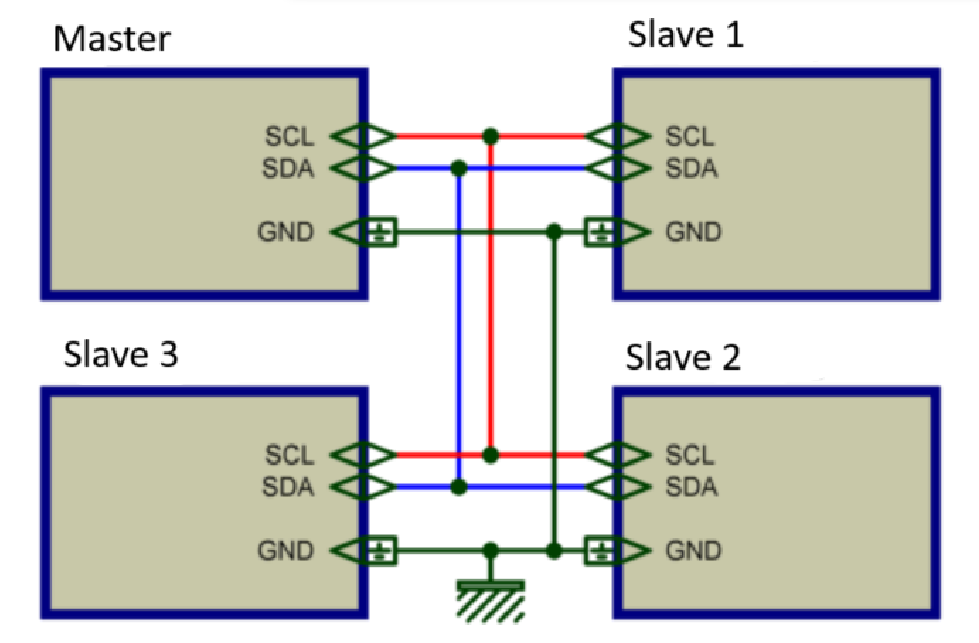
The I2C protocol is a synchronous serial communication protocol. It uses two wires:- SDA (Serial Data): Transmits the data.
- SCL (Serial Clock): Synchronizes communication.
I2C follows a master-slave model, where the master controls the clock and selects the slave to communicate with by using a unique address for each slave. The master sends this address over the SDA line, and the slave receives the data sent. Communication is bit by bit, and each transmitted byte is followed by an acknowledgment (ACK) bit to ensure data reception. I2C supports various communication speeds: Standard (100 kb/s), Fast (400 kb/s), Fast Plus (1 Mb/s), High-Speed (mostly 3.4 Mb/s, but be careful this one is not standardized, it can depends on manufacturer).
When implementing I2C communication in microcontrollers, the HAL (Hardware Abstraction Layer) simplifies interaction with the hardware by providing an interface. It allows easy management for I2C transactions without dealing with low-level hardware details. The HAL supports different types of transactions, including Master Transmit, Master Receive, and Combined Transactions, enabling integration with various I2C devices.
I2C can connect up to 128 devices as each device requires a unique 7-bit address. It is effective over cable lengths of up to about 1 to 5 meters like UART it depends of speed communication. The faster the speed, the shorter the cable must be.
-
Diagram

-
Advantages
- Simple wiring.
- Supports multiple devices and multi-master setups.
- Acknowledgment of data reception.
-
Disadvantages
- Relatively low speed.
- Limited bus length.
- Short cable length
-
Usage
A temperature sensor like the LM75 or an accelerometer like the MPU6050 can communicate with a microcontroller via I2C.
SPI
-
Operation
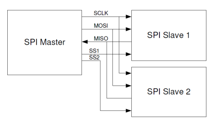
SPI is a fast, synchronous serial communication protocol. It requires four wires:- SCK (Serial Clock): Clock signal line.
- MOSI (Master Out Slave In): Master-to-slave communication.
- MISO (Master In Slave Out): Slave-to-master communication.
- SS (Slave Select): Allows the master to select the slave it wishes to communicate with.
The master selects the slave by sending a signal on the corresponding SS line. Once selected, bidirectional communication begins via the MOSI and MISO lines, synchronized by the SCK clock signal.
The SPI controller operates at variable speeds, limited by the capabilities of the microcontroller, cable length, interference, and the characteristics of the SPI devices. Common clock frequencies range from 1 to 50 MHz. The maximum bit rate (bps) is determined by the SPI clock frequency and the number of bits per transfer. For example, at 10 MHz, the rate can reach 10 Mbits/s. The effective rate also depends on bus management and read/write operations.
With SPI, the only limit to the number of slaves is actually the availability of Slave Select (SS) pins on the master. The effective cable length is typically limited to about 1 to 3 meters due to signal integrity issues.
-
Diagram

-
Advantages
- High speed.
- Simple protocol.
-
Disadvantages
- Requires four wires.
- No acknowledgment mechanism for data reception.
- Only one master.
- Short cable length
-
Usage
SPI is used for applications requiring fast communication, such as interfaces with LCD screens.
Comparative table
| Protocol | Type of Communication | Number of Wires | Max Speed | Number of Devices | Advantages | Disadvantages |
|---|---|---|---|---|---|---|
| UART | Asynchronous | 2 | 1.5 Mbps | 2 (point-to-point) | - Simple to implement - Fewer wires needed |
- Limited to two devices - Risk of desynchronization |
| I2C | Synchronous | 2 | 3.4 Mbps | Up to 128 | - Simple wiring - Supports multiple devices |
- Relatively low speed - Limited bus length |
| SPI | Synchronous | 4 | 50 Mbps | Limited by SS pins | - Very fast - Simple protocol |
- Requires four wires - No acknowledgment mechanism |
Conclusion
In conclusion, serial communication protocols like UART, I2C, and SPI offer different solutions to meet the needs of embedded systems. UART is notable for its simplicity and ease of implementation, being well- suited for point-to-point communication. I2C is highly useful in multi- device setups, allowing a master to control multiple slaves with minimal wiring. Finally, SPI, with its speed and simplicity, is ideal for applications requiring high-speed data transfers, although it requires more communication lines.
The choice of communication protocol depends on the specific application requirements, such as the required transmission speed, the complexity of the architecture, and the number of devices to connect.
To go further :
This article goes into more detail about the different protocols
If you want to learn more about I2C, UART, SPI.
Bibliography :
Microcontroller Connection Protocols: W1, I2C, SPI, UART :
https://medium.com/geekculture/microcontroller-connection-protocols-w1-i2c-spi-uart-7625ad013e60
How microcontrollers communicate with other peripherals? Difference between SPI, I2C, UART, CAN& USB :
I2C: I2C microcontroller basics:
https://www.ti.com/video/series/precision-labs/ti-precision-labs-microcontroller-communication.html
Communication Protocols in Microcontrollers Explained
https://www.homemade-circuits.com/communication-protocols-in-microcontrollers-explained-%EF%BF%BC/
I2C
https://fr.wikipedia.org/wiki/I2C#:~:text=I2C%20 https://www.ti.com/lit/an/sbaa565/sbaa565.pdf?ts=1725867496251&ref_url=https%253A%252F%252Fwww.google.com%252F#:~:text=I2C%20is%20a%20two%2Dwire,and%20receive%20commands%20and%20data. https://www.circuitbasics.com/basics-of-the-i2c-communication-protocol/
UART
https://fr.wikipedia.org/wiki/UART https://www.circuitbasics.com/basics-uart-communication/ https://www.multipower.fr/ressources/blog-2/protocole-uart/ https://www.analog.com/en/resources/analog-dialogue/articles/uart-a-hardware-communication-protocol.html
SPI
https://fr.wikipedia.org/wiki/Serial_Peripheral_Interface https://www.circuitbasics.com/basics-of-the-spi-communication-protocol/ https://eduscol.education.fr/sti/sites/eduscol.education.fr.sti/files/ressources/techniques/3300/3300-le-bus-spi.pdf https://community.nxp.com/t5/LPC-Microcontrollers/Maximum-SPI-Clock-Speed/m-p/1190312