- Prerequisites
- Introduction
- Development Environment
- Understanding the Boot Process on ARM
- First Bare-Metal Boot
- Conclusion
- Sources
Prerequisites
This article is intended for developers who are curious about kernel development and want to explore what happens behind the scenes when a computer boots.
While no prior experience in operating system or kernel development is required, a few foundational concepts will help you get the most out of this guide. You should have a basic understanding of how modern computers work: processor architecture, assembly language (arm64), and how source code is transformed into a binary through the compilation and linking process.
Since I won’t go over Arm64 instructions in detail here, I recommend referring to this Arm A64 Instruction Set Architecture if you’re not familiar with them.
It’s also important to have a general idea of how an executable is laid out especially how sections like .text, .data, and .bss are structured within a binary.
That said, you don’t need to know anything about kernel development or Rust to follow along. I personally started from scratch, and this article is meant to reflect that learning journey.
However, if you’re completely new to Rust, reading through The Rust Programming Language Book will greatly help you understand the syntax and patterns used throughout the code.
Introduction
The goal of this article is to walk through the first steps of writing an operating system for the ARM64 architecture using Rust. We’ll start from the very beginning, no existing OS, no firmware, just a bare-metal machine and our own code.
One of the main reasons we’re using Rust to build our kernel is its strong focus on memory safety without relying on a garbage collector. Unlike C or C++, Rust ensures that many classes of bugs (like buffer overflows or use-after-free errors) are caught at compile time. This is especially important in kernel development, where such bugs can crash the whole system or introduce security vulnerabilities.
Rust also guarantees no undefined behavior by default, which adds an extra layer of reliability when writing low-level code. Because of these features, Rust is gaining traction in OS development and is being adopted by major projects such as the Linux kernel.
Instead of diving straight into hardware drivers or complex kernel internals, we’ll begin by understanding how a computer boots, what a bootloader really is, and how we can implement one ourselves to load and launch a kernel written in Rust.
This journey is all about demystifying the boot process, especially on ARM systems. If you’ve ever wondered how your code gets from storage into execution, this is exactly what we’ll uncover.
We’ll work on real-world concepts like:
- How the ARM boot process is structured, from ROM to OS.
- What expectations Linux has when booting on an ARM system.
- How to simulate all of this using QEMU, so we can develop without dedicated hardware.
And, importantly, we’ll write everything ourselves: the bootloader in assembly, and the kernel in Rust, building up a working system and learning how all the pieces fit together.
By the end of this article, we will have a minimal system that can boot in QEMU, load a Rust kernel, and respect the Linux ARM boot protocol. It won’t do much at first, just display a message on the screen, but it’s a necessary first step toward building a fully functional kernel.
Development Environment
Cross-Compilation
Before we can run code on our ARM64 target, we have to solve a key problem: a binary compiled on one machine won’t necessarily run on another. That’s because different CPU architectures (like x86_64 and ARM64) use completely different instruction sets.
To deal with this, we use cross-compilation: building code on one system (the host) to run it on another (the target). This is essential when working with bare-metal environments or embedded systems, where the target might not have the resources or OS needed to compile code itself.
In our case:
Host: your development machine (usually x86_64 with Linux/macOS/WSL).Target: a virtual ARM64 board (QEMU virt).
That’s why we use the GNU aarch64-linux-gnu- toolchain, it allows us to assemble and link everything (like the bootloader written in assembly and the Rust-compiled kernel) into a format that the ARM64 machine can actually understand and run.
Rust Toolchain
To get started, first install Rust and it’s build system Cargo if you haven’t already. Once installed, reload your shell or open a new terminal, then add the AArch64 bare-metal target with the following command:
|
|
This tells Rust that we want to compile for an ARM64 system without an operating system, which is known as a freestanding environment. This is essential when writing low-level code like a kernel, where we can’t rely on any OS-provided services or standard libraries.
Understanding the Boot Process on ARM
Writing the Bootloader
What Is a Bootloader?
A bootloader is a low-level program that serves as a critical bridge between the raw hardware state of a system at power-on and the execution of a high-level operating system. When a system powers up or resets, the CPU begins executing instructions from a fixed memory location (called the reset vector). At this point, the system is in an uninitialized state, and it’s the bootloader’s responsibility to set up the minimal environment required for the kernel to run.
The bootloader performs several key tasks:
- Hardware Initialization: Configures the CPU, disables/enables caches, sets up exception levels, and initializes peripherals like UART.
- Memory Configuration: Sets up RAM regions, clears uninitialized memory (BSS), and sometimes sets up MMU and page tables.
- Kernel Loading: Locates the operating system kernel binary (e.g., from flash memory), copies it into RAM.
- Parameter Passing: Prepares information like the location of the Device Tree Blob (DTB).
- Execution Handoff: Transfers control to the kernel’s entry point with the CPU in the expected mode and state.
Bootloaders in Embedded Systems
Unlike PCs, embedded systems (e.g., smartphones, routers, development boards) do not rely on BIOS or UEFI. Instead, they use custom boot sequences and firmware written for specific SoCs.
ROM Code / First Stage: On reset, the CPU executes code from on-chip ROM (called the boot ROM or mask ROM). This first-stage loader (provided by the chip vendor) is responsible for loading a secondary bootloader from flash, eMMC, SD card, etc.
Second Stage Bootloader: This is typically user-provided (e.g., U-Boot) and is responsible for initializing DRAM, copying the kernel from non-volatile memory to RAM, and passing control to the kernel.
On ARM systems, this process is highly SoC-dependent. The bootloader must respect strict architectural rules, including exception level transitions (EL3 → EL2 → EL1), cache management, and DTB loading.
Our Case: QEMU -M virt, ARMv8-A and AArch64
In our project, we emulate an ARMv8-A system using QEMU with the following configuration:
qemu-system-aarch64 \
  -M virt,virtualization=on,gic-version=3 \
  -cpu cortex-a53 \
  -nographic \
  -drive if=pflash,format=raw,file=pflash.bin
Let’s break this down:
-M virt: Uses a virtual board designed by QEMU for ARMv8-A with generic peripherals.cortex-a53: A 64-bit ARM core (AArch64), typical in embedded/mobile SoCs.-drive if=pflash,...: Emulates a flash memory, where the bootloader and kernel image are stored.
On this platform:
- The CPU starts executing at address
0x00000000, where the bootloader resides (mapped from the flash). - Our bootloader’s job is to load the kernel (stored at offset
0x00100000in flash) into DRAM (0x40000000) and jump to its entry point. - This mimics a real-world system with ROM-based first-stage firmware and DRAM-mapped execution.
For this article, we will not implement a multi-stage bootloader. Instead, we will keep things minimalistic and focused on clarity.
Let’s Dive into Writing a Bootloader
Now that we understand the theoretical foundations, we’re ready to write a bootloader to see these steps in action. To guide our implementation, we’ll follow the Linux Boot Protocol AArch64, which defines how the kernel expects to be loaded and executed. This protocol is also used by U-Boot, one of the most widely adopted bootloaders in embedded systems. By aligning with this standard, we ensure our minimal bootloader remains compatible with Linux and reflects real-world practices.
Setup and initialise RAM
We previously saw that our machine begins execution at address 0x00000000, which typically maps to a non-volatile flash memory region. In our setup, this flash will contain three key sections laid out sequentially:
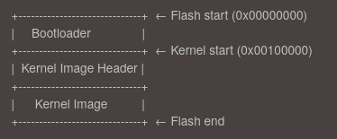
This layout allows the bootloader to locate both the kernel header and the kernel binary without requiring a filesystem or complex storage interface. However, the kernel cannot run directly from flash - it must be relocated to RAM first.
This step corresponds to the first mandatory requirement in the ARM64 Linux boot protocol:
“The boot loader is expected to find and initialise all RAM that the kernel will use for volatile data storage in the system.”
After initializing the RAM, the bootloader will copy the kernel image from flash into a suitable location in RAM and prepare to transfer control to it. This relocation step ensures faster execution and enables the kernel to manage memory efficiently from the start.
As you can see on the diagramm, before the kernel image itself, the bootloader must read a small 64-byte header that provides important metadata about the kernel binary. This header helps the bootloader understand where and how to load the kernel into memory.
The header is structured roughly as follows:
u32  code0;                              /* Executable code */
u32  code1;                              /* Executable code */
u64  text_offset;                        /* Image load offset, little endian */
u64  image_size;                      /* Effective Image size, little endian */
u64  flags;                                /* Kernel flags, little endian */
u64  res2      = 0;                      /* Reserved */
u64  res3      = 0;                      /* Reserved */
u64  res4      = 0;                      /* Reserved */
u32  magic     = 0x644d5241;   /* Magic number, little endian, "ARM\x64" */
u32  res5;                                 /* Reserved (used for PE COFF offset) */
Among these fields, image_size is particularly important because it tells us the exact size of the kernel image that must be copied from flash into RAM. This avoids blindly copying an arbitrary amount of data and ensures the kernel is correctly relocated without corruption.
By parsing this header, the bootloader can determine the offset in flash where the actual kernel binary starts (text_offset) and how many bytes to copy (image_size), which are crucial steps to successfully load and execute the kernel.
The following ARM64 assembly code snippet demonstrates this copying process:
|
|
Key elements in this code are:
FLASH_KERNEL_ADDR: The starting address in flash where the kernel header and image are stored.TEXT_OFFSET: The offset within the RAM image where the actual kernel will be load.RAM_ADDR: The base address in RAM where the kernel should be loaded.KERNEL_SIZE: The size of the kernel image that must be copied.
The bootloader reads the kernel header at FLASH_KERNEL_ADDR, extracts the text_offset and image_size, calculates the exact RAM destination address, then enters a loop copying the kernel 8 bytes at a time until the entire kernel image is transferred to RAM. This ensures the kernel is properly placed in memory and ready for execution.
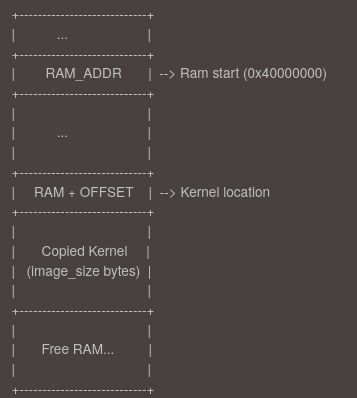
After this the RAM will looks like this:
Setup the device tree
The Device Tree (DT) is a data structure used by the Linux kernel to describe the hardware layout of the system it is running on. It includes information such as available memory regions, CPU configuration, peripheral addresses, and interrupt controllers. This abstraction allows the same kernel binary to support multiple hardware platforms by simply providing a different device tree blob (DTB).
In our case, since we are running on QEMU, the emulator conveniently generates the device tree automatically and places it at the beginning of RAM, typically at address 0x40000000.
You can have a look at this file with the following commands:
|
|
Call the kernel image
Before calling the kernel we have to do some setup.
We start by disabling interrupts early in the boot process to ensure a predictable and controlled execution environment. At this stage, the system is not yet fully initialized: memory, devices, and exception handlers are not set up, so any unexpected interrupt could lead to undefined behavior or a crash.
|
|
Next, we initialize the stack to enable safe code execution. This is essential because the ARM architecture does not automatically configure stack memory, and operating without a valid stack can lead to undefined behavior.
|
|
Before going further, we need to briefly understand Exception Levels (EL) and the initial state of the processor at boot time.
The ARM64 architecture introduces multiple Exception Levels to manage privilege separation and execution contexts:
EL0: User space applicationsEL1: Operating system kernelEL2: Hypervisor mode (for virtualization)EL3: Secure monitor (used by TrustZone, typically reserved for secure firmware)
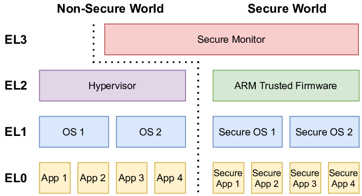
In QEMU, execution starts at EL2 (hypervisor level), following modern boot protocols. This allows the kernel to:
- Configure EL2 settings
- Optionally drop to EL1 if needed
The bootloader checks CurrentEL to verify the level and adapt initialization accordingly, avoiding assumptions about the boot environment.
|
|
This setup includes:
- Disabling the MMU and caches.
|
|
- Resetting timers
|
|
- Preparing access control registers to give the kernel full access to required system features.
|
|
Finally, once the kernel has been copied into RAM and the system is prepared, we can hand over control to the Linux kernel. According to the ARM64 Linux boot protocol, the kernel expects to be entered with the following arguments:
- x0: The physical address of the device tree blob (DTB)
- x1–x3: Reserved and should be set to 0
We also compute the correct jump address based on the kernel’s text_offset value from its header, which tells us where the entry point lies relative to where the image is loaded in memory.
|
|
This jump officially ends our bootloader’s job, transferring execution to the kernel with the expected arguments and a properly initialized environment.
Write Our first rust programm
To build our kernel in Rust, we start by creating a new Rust project using:
|
|
The --lib flag builds a static library for bootloader linking rather than a standalone binary. A bare-metal kernel cannot use Rust’s standard library (std), which depends on OS services, so we use #![no_std] to restrict the code to core (freestanding Rust).
The #![no_main] attribute bypasses Rust’s runtime initialization, allowing a custom entry point (e.g., kmain) to be defined directly.
|
|
The #[unsafe(no_mangle)] attribute disables Rust’s name mangling so that the symbol is exported exactly as kmain, allowing our bootloader to locate and call it. The extern "C" declaration ensures that kmain uses the standard C calling convention. Finally, -> ! means the function never returns, it enters an infinite loop.
Display Hello, from Rust!
One of the first visible effects we want from our kernel is to output a message like “Hello, from Rust!” to the serial port. In QEMU, the UART device is mapped to a memory-mapped address at 0x0900_0000. This means we can communicate with it by writing and reading directly from specific memory locations.
Rust enforces memory safety, so to interact with raw memory-mapped hardware, we must use unsafe code. Here’s how we write a character to the UART:
|
|
Let’s break it down:
- UART base address points to the memory-mapped UART device.
- Flag Register at offset
0x18tracks status; Bit 5 (TXFF) checks if the transmit FIFO is full. - The code polls until
TXFFclears (FIFO has space), then writes a character to the transmit register viawrite_volatile(ensures the write isn’t optimized away).
Finally, the print() function in your code simply calls putchar() in a loop over the byte slice:
Panic Handling
Since we don’t have an OS to handle panics, we use:
|
|
and implement a minimal panic handler (often an infinite loop or a hlt instruction). To avoid linking errors and reduce binary size, we configure Rust to use an abort strategy:
|
|
Arm64 Headers
In addition to our main kernel logic, we must prepend a specific 64-byte header to comply with the ARM64 Linux boot protocol. This header acts as a contract between the bootloader and the kernel, describing how and where the kernel should be loaded and executed.
|
|
Each field in this header serves a specific and critical role, the most important ones:
-
code0Branch instruction (0x14000010) which corresponds to:b 0x40This is a branch instruction that skips 64 bytes, the exact size of the header, jumping directly to the start of the actual kernel code.
In ARM64, all instructions are 4 bytes. The opcode
0x14000000represents ab(branch) instruction, and the offset (0x10) means “jump ahead 16 instructions” (16 × 4 bytes = 64 bytes). So0x14000010(0x14000000 | 0x10 = 0x14000010) tells the CPU to skip the header safely to go directry to kernel code.Without code0, the CPU would try to execute the header as code, which would cause a crash. By placing a valid branch instruction here, we ensure smooth handoff from the bootloader to the kernel because
code0is the first instruction that gets executed when the bootloader jumps to the address where the kernel was loaded in memory. -
text_offsetOffset from the load address where executable code begins (e.g.,0x80000). Allows the bootloader to relocate the kernel flexibly. -
image_sizeNumber of bytes to copy from flash to RAM. Must be patched post-compilation since the final binary size is unknown beforehand. -
magicFixed signature (0x644d5241, ASCII"ARM\x64"), ensuring the bootloader loads a valid ARM64 kernel.
Configuring the Linker Script
The linker script controls how our kernel binary is laid out in memory.
OUTPUT_FORMAT(elf64-littleaarch64)
OUTPUT_ARCH(aarch64)

TEXT_START = 0x40080000;

SECTIONS {
    . = TEXT_START;

    .text.header : {
        KEEP(*(.text.header))
        . = ALIGN(64);
    }

    .text : ALIGN(64) {
        *(.text._start)
        *(.text .text.*)
    }
    ...
}
Here’s a breakdown of the key elements:
OUTPUT_FORMAT / OUTPUT_ARCH: Specifies that we are building an ELF binary for the AArch64 (ARM64) architecture.TEXT_START = 0x40080000: This defines where the kernel will be loaded in RAM and begin execution..text.headerPlacement- Positioned at memory start with 64-byte alignment (
ALIGN(64)) - Contains the kernel header that bootloaders expect at a predictable location
KEEP()ensures the section isn’t optimized out during linking
This layout ensures the kernel image is structured correctly for the bootloader to load, parse the header, and start executing from the expected memory location
- Positioned at memory start with 64-byte alignment (
The current linker script is missing critical sections like .bss that are essential for proper kernel operation, for more details on how to add them you can visit these links:
First Bare-Metal Boot
Now that everything is ready, the last step is to test our kernel. But before we can do that, we need to create a binary image that includes both our bootloader and kernel. To automate this process, we write a Makefile that handles all build steps from source to final image. You can find the whole Makefile on my github.
Step 1 – Assemble the Bootloader
|
|
The bootloader source file (boot.S) is assembled into an object file using the ARM64 assembler.
|
|
The object file is then converted to a raw binary using objcopy. This binary is what will be placed at the beginning of our flash image.
Step 2 – Compile the Kernel
|
|
The Rust kernel is compiled as a static library (libkernel.a) using Cargo.
Step 3 – Link the Kernel
|
|
We link the compiled kernel library into an ELF binary using a custom linker script. This script, as we’ve seen before, ensures all kernel sections are mapped to the correct virtual and physical addresses.
Step 4 – Generate Binary and Patch the Header
|
|
The ELF binary is stripped into a flat binary.
|
|
After the binary is created, we calculate its final size (aligned to 8 bytes) and patch the image_size field in the kernel’s 64-byte ARM64 header at offset 16.
This is necessary because the bootloader relies on this field to determine how many bytes to copy from flash to RAM. The patching happens after compilation, since the final size of the binary is not known until the ELF is fully built.
Step 5 – Create the Flash Image
|
|
We create an empty 64 MiB binary image to simulate a flash device.
|
|
The bootloader is inserted at offset 0x00000000, where the CPU starts execution.
|
|
The kernel is inserted at offset 0x00100000 (1 MiB), which matches what the bootloader expects when copying the kernel into RAM.
Running QEMU
We are now ready to launch QEMU, which allows us to simulate an ARM machine with our binary stored in flash memory.
To do this, we use the following command:
|
|
If everything goes well, you should see output on your terminal Hello, from Rust!.
Conclusion
We have successfully booted our ARM64 kernel by loading all code from flash memory through our custom bootloader, fully complying with the Linux Boot Protocol requirements. This clean, standardized approach gives the kernel immediate control at EL2 with properly initialized memory.
However, this contrasts sharply with traditional x86 PC boot processes. x86 systems begin with firmware (either legacy BIOS or modern UEFI) executing from ROM, performing hardware detection through POST before engaging multi-stage bootloaders. These must navigate legacy constraints and complex handoff procedures between firmware stages. While more cumbersome, both architectures ultimately achieve the same goal - delivering control to the kernel in a prepared system state.
Sources
- Arm A64 Instruction Set Architecture
- The Rust Programming Language Book
- Rust and it’s build system Cargo
- Device Tree Blob (DTB)
- Linux Boot Protocol AArch64
- U-Boot
- Theory behind bootloader
- Explanation about linker scripts
- How to write a linker script
- QEMU specifications
- Rust embedded development
- Register setup