Not So Noiseless, ART of UARTS, part 1
Introduction
I believe in a conspiracy : Giant tech companies make things easy so we get dumb enough to not know how to live without their overpriced garbage. Everyone knows that computers connect to network, download, upload, ping and pong each others as if there were no tomorrow? They do all these things so often and so quickly that we tend to forget that we pretty much have no idea what happens in the background. Wake up sheeple! Don’t you see! The Giants are at it as we speak! Come with me brother, sister; come with me make our own life as hard possible as we recreate the very first thing any modern machine needs to perform on a network.
Scope of the article
We assume :
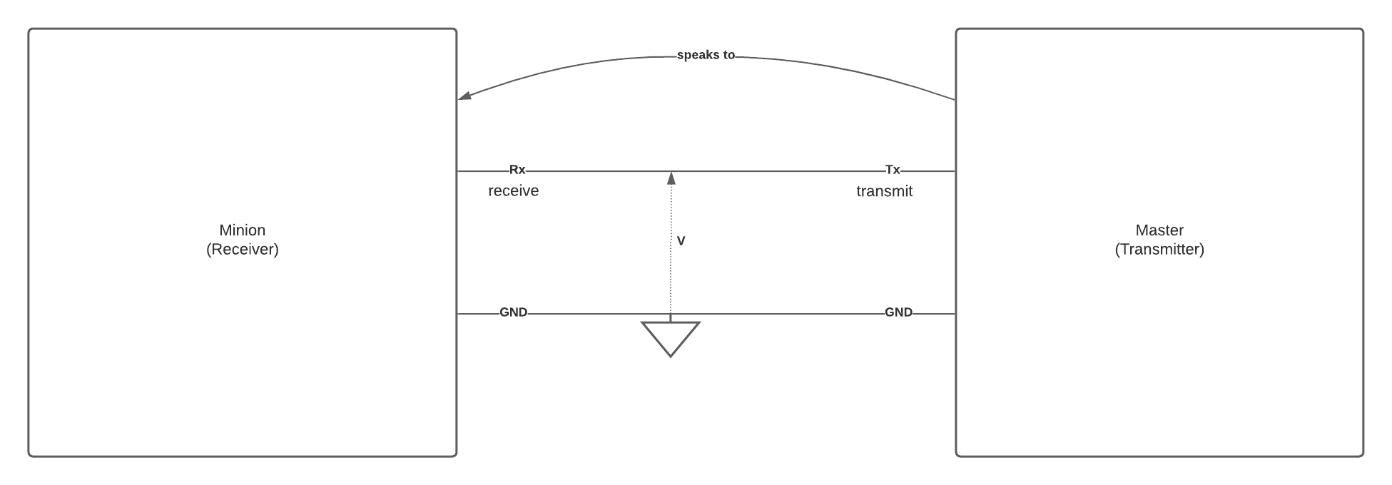
- Have two computers in a master-minion relationship1.
- Master: is talking
- Minion: is listening
- The reader has a basic understanding of voltages.
- The reader has some basic knowledge of binary numbers, the ascii table and basic electronic.
We will only deal in the theory of UART and will delegate actual UART building and designing to another article of the series ”The Art of UARTs”.
Errata
This is the third version of this article. Some sentences were re-written for clarity sake’s and typos were removed. The section ”Making your own UART” has been stricken as it was becomming too long and disjointed from this article; I have decided to make ”The Art of UARTs” a series of article instead. This article now only deals in the theory of UARTs and has been renamed as such. A bibliography has been added. Furthermore, I would like to thank everyone who has given their time for constructive criticism. I’ve taken into consideration every piece of critic in your comments.
Justifying the A in UART
The importance of digital over analog
The trivial way to make a computer speak would be for the one that is speaking to lower or raise the voltage of single shared line connecting the computers to send the raw data. This would be a perfectly fine solution if it wasn’t terrible in so many aspects.
One reason is that a cable should be used to either send $1$ or a $0$. Ultimately, computers store binary information, most likely, as a high or low voltage.
Allowing a cable to have more than two meaningful states implies there is going to be an analog to digital conversion going behind the scenes on the minion side and digital to analog conversion master side. ADCs2 are expensive and slow and therefore to avoid like the plague. We would rather use something cheap, fast and simple: a resistor and nothing else. The cable holds the data as the minion reads it.3 states will be :
- High : $(V = V_{cc})$
- Low : $(V = −V_{cc})$.
Any in between $(-V_{cc} < V < V_{cc})$ shall either be : considered as one of the two states4 or be meaningless.
Info
The minion must read HIGH states or LOW states only this is the two states rule.
The digital is analog
As much as we don’t want it to, a digital signal is an analog electrical signal. The perfectly square signal (fig 3) is a fantasy. The transition phase from a HIGH to a LOW is a problem : What value will the minion read during a state transition ?
Avoiding data corruption should be a priority when trying to implement a communication system; we must not risk the minion reading an illegal state. Furthermore, we may not use the ”neither clearly high nor low” voltage window as an ”IDLE” state as it would mean having three state on the cable (High, Low, and Idle)6 which, as we’ve seen, something we would rather avoid. We must make sure the minion always understands a 1 or a 0 from each read.
Return to zero bipolar signal
Assume the minion receives the signal in figure 2. We arbitrarily decide to use HIGH = 0 and Low = 1;
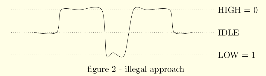
It is clear that using midway voltage as IDLE time is illegal as it leaves us three states to deal with. Therefore, IDLE times may not be distinguished from HIGH and LOW. We shall protect the minion from ever reading an IDLE7.
A truly digital signal
In a perfect world, the minion would receive this:
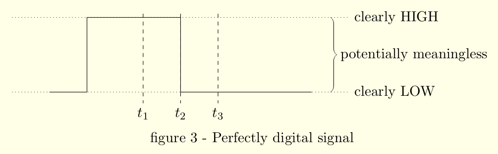
All three reads are fine. There might be a protocol issue with t2 as there is no telling if the minion would take this read as HIGH or LOW but it is not our problem. This signals considered, all reads are strictly HIGH or LOW which satisfies our two states rule. Yet, the world doesn’t work that well and beautiful square functions are much too rare. In real life, we should expect rise and drop time.
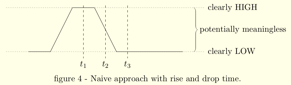
In which case we should expect reads in less than ideal times (see $t_2$). Careful consideration of when the reads occurred must be put. This is a synchronization problem.
Cable cost
cable shielding
Without getting too involved in physics, a magnetic field around a cable implies a current in the cable, even if the cable is not the source of the current8. Therefore, a cable may be victim of nearby objects’ magnetic fields. This is why cables often come with a shield.
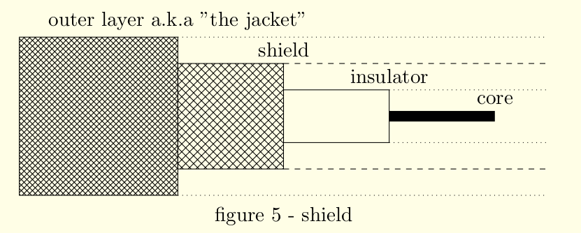
The core is covered (and separated) by a braided copper surface that acts as a Faraday’s cage. This makes the cable significantly more expensive and larger but mitigates the effect of external magnetic fields and to a lesser extent capacitive crosstalk.
Capacitive Crosstalk
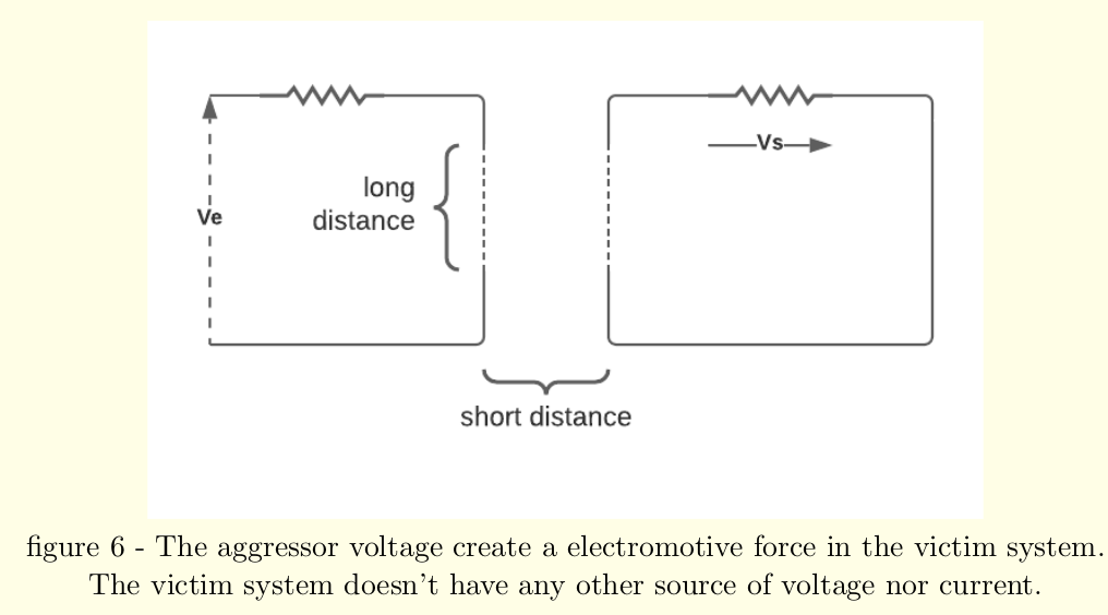
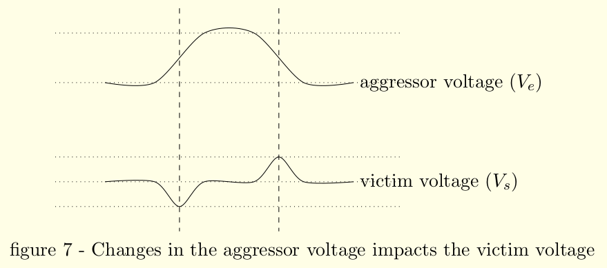
Counter intuitively, two cables do not need to be connected to each other to crosstalk. As any good physician would tell you: a change of current in a cable creates an electric field around the cable. We should expect a system similar to (figure 6) to produce a magnetic field each and every time the current changes. The magnetic field produced by one line may disturb the other(figure 7).
The more cables we have, The longer the distance we have to transmit, the harder it is to preserve the integrity of our message.
The skin effect
Warning
This section assumes the reader has a sound understanding of Fourrier series decomposition.
Tip
This section may be skipped safely.
One unsuspected behavior of current is that the more unstable the current is, the less electrons like to travel near the center of a surface of a cross cut perpendicular to the electron flow. This is called the skin effect (figure 8).
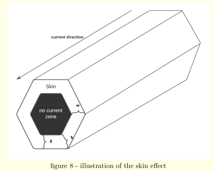
The less area is available for electrons to pass through, the higher the resistance of the cable. As seen in the following formula for $\delta$, the skin width depends on the signal’s temporal frequency $f$, assuming the signal is a sinusoïd. For custom signals (for example, the data over a transmission line), the skin effect must be calculated for each harmonic.
$$\delta_n=\frac{1}{\sqrt{\sigma\mu\pi f_n\ }}$$- $\delta_n$ skin width for the in $n^{th}$ harmonic
- $\sigma\mu$ a material dependent constant ($\sigma_{copper}\mu_{copper}\approx72,25 \left[\frac{S \cdot H}{m^2}\right]$)
- $f$ frequency of the harmonic in $Hz$
It is interesting to point out the skin effect width is independent from the girth of the cable. Therefore, it is much more interesting to use multicore cable (see figure 9).
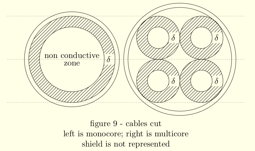
On figure 9 Both cables use the same amount of material. Yet the multicore cable suffers significantly less from the skin effect. To save on material cost, cables need to be engineered.
Info
Manufacturing cables against the skin effect is expensive and makes them bigger.
On synchronization by shared clocks
A common solution in electronics for such problem is what is called a shared clock.
The master tells the minion to read by setting the clock signal to a certain state which is recognizable by the minion.

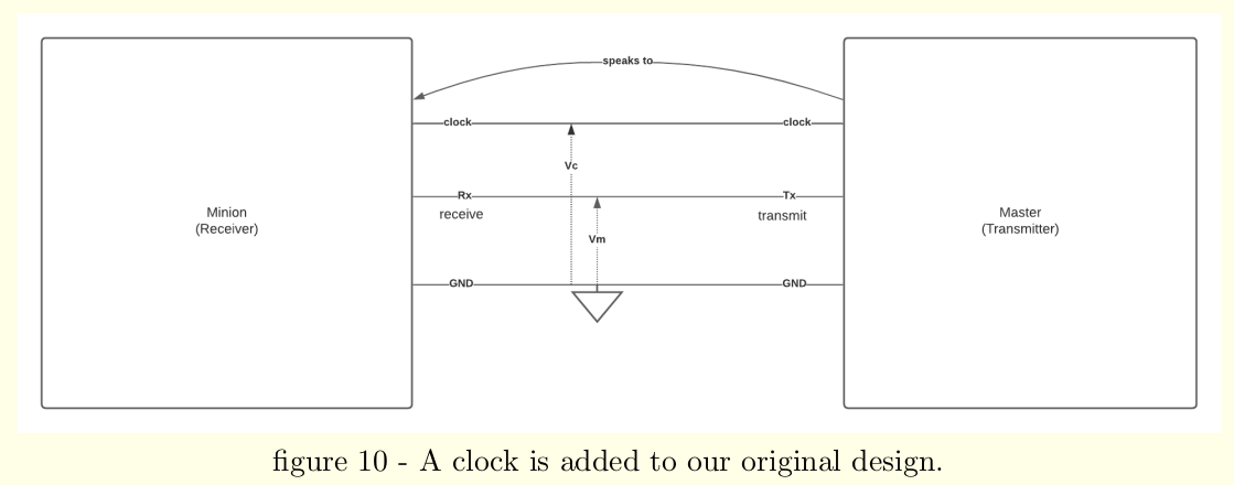
This solution is very elegant as it solves many problems that occur with synchronization. But this solution is viable if (and only if) the clock signal is synchronized with the Rx Signal. Figure 10 shows that the communication line ($V_m$) has two ends: Rx (Receiver) and Tx (Transmitter); it is not only for pin assignment, it also shows that the signal might be different between Tx and Rx.
Info
For any time $t$, there is NO guaranty that: $R_x(t) = T_x(t)$
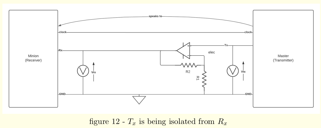
As a rule of thumb, it is safe to assume Tx to be synchronized with the clock (otherwise the transmitter itself is to blame for producing unreadable signals). Rx should be measured on the cable; for cables more than a few meters, the closer to the receiver, the better9. Tx should be measure un-coupled from the transmission cable (with an operational amplifier for instance) like on figure 12.
As we will see in the dedicated subsection, damaged states of the clock or Rx may desynchronize the data from the clock. Desynchronization and the cost of sending data through cable skyrocketing over long distance, the clock is a viable solution for small distances (generally intramachine) communication only.
Conclusion
We will have to make do without a clock because of the added expenses for the clock line. Communication without a clock is said to be asynchronous. This is somewhat of a misnomer as communication must be somewhat synchronized: whether a clock is shared or not.
Info
A transmission is asynchronous if and only if there is no shared clock between the transmitter and receiver.
Tip
The receiver may have its own clock for its own purposes. As long as the receiver and transmitter do not share a clock, the transmission is asynchronous.
Protocol
We must avoid illegal reading states, yet, we do not have access to a clock. Therefore, the protocol itself must help the receiver to synchronized itself with the transmitter.
Metadata: bauds and bits
The Internet-savvy individual already knows that data is sometime transferred with some extra’s called metadata (the data about the data). They are not meant for the user but the hardware and software to handle the real message in the background. As they are not meant for the user, they are, sometime, not shown to the user. This is a pain for hardware makers as a $n\frac{bit}{s}$ capable piece of equipment will actually be slightly slower because some “bits” are used for metadata.
The term “baud” is used as disambiguation to $\frac{bit}{s}$ to differentiate the transmission speed (message + metadata) to the internet speed (message only).
Info
The baud refers to the speed at which actually transferred (gross speed) while $\frac{bit}{s}$ refers to user experienced speed (net speed).
Info
baud rate is synounymous to “number of baud”
Schmitt’s Trigger
There is a way to sanitize the state of a signal into HIGH or LOW : “A Schmitt’s Trigger”. It is a piece of equipment that output a digital signal (HIGH or LOW) depending of triggers activated by an analog signal.
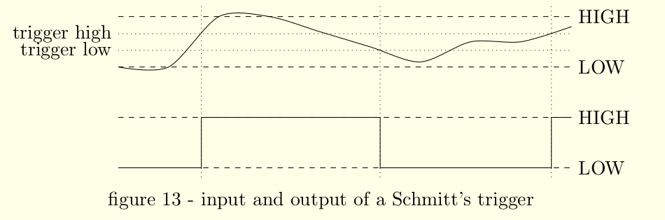
The output is a digital signal but is not yet good for reading as Schmitt’s triggers are designed too far apart from each-others to allow constant triggering from the signal noise and therefore tend to react a bit late (see figure schmitt). Furthermore, the way Schmitt’s triggers are implemented often left us with slightly unpredictable detection performances : the edges might be slightly late or early.
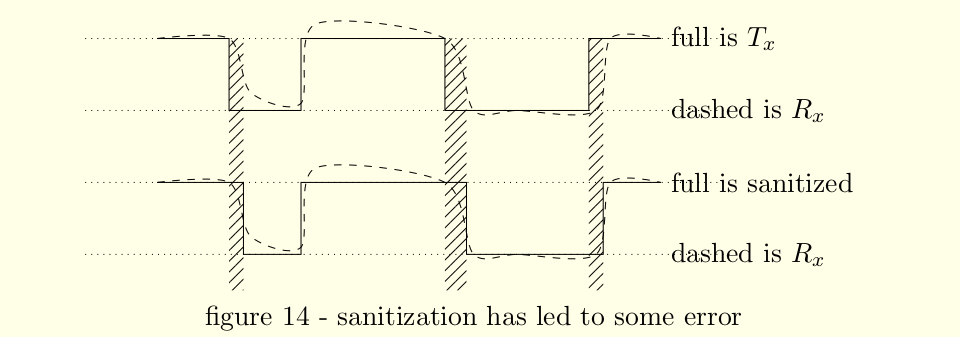
We will use Schmitt’s triggers to help the receiver to synchronize itself with the transmitted message.
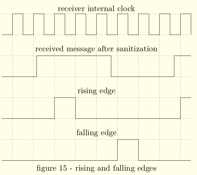
Rising and Falling edges
There is a point to register the moment the trigger has detected a switch. We detect the rising edge when the trigger goes from LOW to HIGH and a falling edge the other way around.
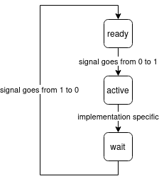
Rising and falling edges detector are extremely cheap and easy to do. It is a state machine with three (3) states : (A) ready, (B) active, (C) waiting. On each clock cycle, the machine as one opportunity to go to next step (with C cycling back to A).
Baud rate detection
It is highly recommended the baud rate to be known in advance by the receiver as most serial strategies in use are unlikely to offer quick and easy solution to guess the speed. Assuming figuring out the baud rate is a necessity, here are a few tips:
Letting the hardware decide
The transmitter can purposefully send the character $0x55 = b'1010101$. If the receiver expects this message, it may measure the length of HIGH and LOW and let the hardware deduce the speed. Once the baud rate is known, the receiver may read the following transmitter messages correctly.
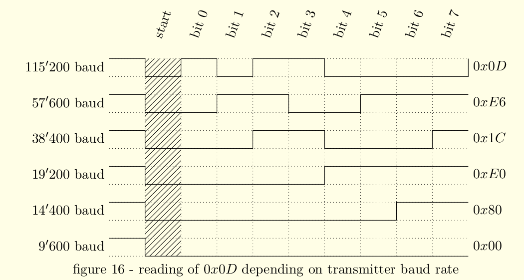
Letting the software decide
This method is proposed by Texas Instrument on their paper : Automatic Baud Rate on the MSP430 written by Chuck Farrow. The transmitter can purposefully send the character 0x0D (carriage return). The receiver must have set its own listening baud rate to 155’200 baud. Assuming big-endian and the transmitter using one of the following baud rate shown on the figure 16 :
RS232
There are many protocol for serial communication. We will take a look at RS232 for its ubiquity; most of computer serial port are RS232 capable if not RS232 capable only. RS232 has multiple parameters that are expected to be known and identical by both receiver and transmitter:
Info
Most parameters for RS232 are not supposed to be detected by the receiver in any way but preprogrammed instead.
It is assumed these parameters are known in advanced by both the receiver and transmitter.
baud rate
Usually one of the following values:
- 115 200
- 57 600
- 38 400
- 19 200
- 14 400
- 9 600
Info
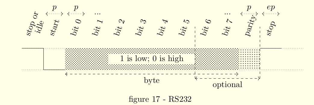
in figure 17
$$p = \frac{1}{baud\ rate}\qquad [s]$$byte size
Rs232 sends message as frames and each frame comes with data and metadata. The byte size refers to the length of the message, namely, the data without the metadata. In case of doubt, see figure 17. May be 5, 6, 7, 8 bits long10
Info
$$byte\ size \in \{5, 6, 7, 8\}\qquad [bits]$$
parity
The parity bit is usually used for error correction. They are three usual parameters :
- none: the transmitter goes to end right after message
- even: the parity bit is calculated for the frame to have an even amount of bits
- odd: the parity bit is calculated for the frame to have an odd amount of bits
The parity may be used has ’extra bit’ for the frame, it is sometime refered as bit 9 or CS9. These two states for the parity parameter are called :
- mark: parity is 1, regardless of previous number of bit set
- space: parity is 0, regardless of previous number of bit set
stopbits
The signal must come back to IDLE before leaving in order to chain frames. That Idle must be at least $p$ seconds long. stopbits period refered as $e \cdot p$ on figure 17. Usually $e \in \{1, 1.5, 2\}$ but not necessarily.
$$ stop\ bits\ \Rightarrow e \cdot p\ \geq\ p $$Start bit and synchronization
The start bit may (and should !) be used to synchronize the minion with the master. We know that the signal is somewhat unpredictable near bit transitions. Therefore, the minion should try to offset its reading attempt to hit the middle of each bit. The trick is to detect to falling edge of the start bit and offset the reading from one and half the expected reading period for the given offset.
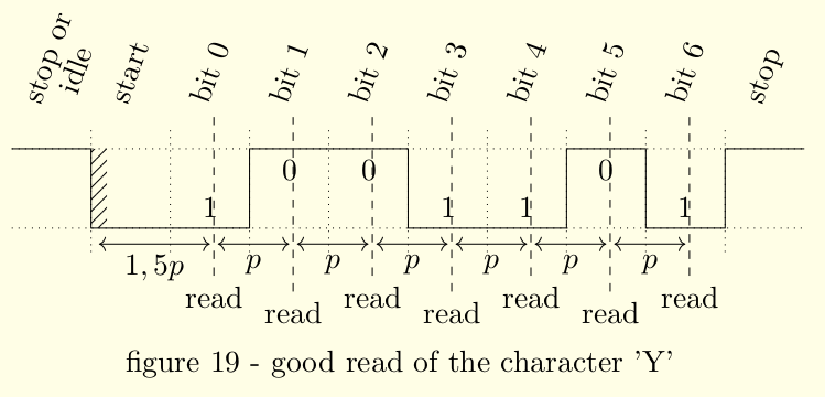
The common strategy to do so is oversampling by which the receiver clock frequency is set multiple times over the baud rate, let say $s$ time over. When the start bit is recognized, the receivers waits for $\frac{2s}{3}$ clock tics. the receiver’s uart then perform a read once every $s$ clock ticks.
Conclusion
Here we are, if you’d were to implement your own computer one day, making it chit-chat should not be an issue ! You know how to deal with the main concerns of communication over reasonable distances, one robust protocol that doesn’t that hard to implement; id est Omnia sunt bona … assuming you’d had the goods.
In the next chapter of this article line, we’ll look into the in-n-outs of the prototyping of our own handmade UART.
See you then electric cowboy.
Bibliography and further reading
Usage and point of serial over parallel communication
- what to do with a serial port
- what do you mean parallel is slower than serial ?
- more on parallel data transmission issues
More on ADC, analog communications and their innacuracies
ADC3563 16-Bit, Low-Noise, Low Power ADC from Texas Instrument case study
- some very high speed adc
- at the time of the writing, they cost around 51$ per unit for a 1'000 order
Skin effect
RS232
- Automatic Baud Rate on the MSP430 written by Chuck Farrow
- this article takes a deep look into the db9 connector. It is much less complicated than it looks like. Especially when you remember than only two or three lines only are necessary and the rest are for other kind of serial communication.
Schmitt’s Trigger
-
Previously master-slave relationship ↩︎
-
An ADC(analog to digital converter) is piece of hardware that, given a voltage as input, outputs a binary number proportional to the input ↩︎
-
The cable might have a stronger voltage than the minion can handle; hence the resistor ↩︎
-
See Schmitt Triggers ↩︎
-
the signal shall not be considered a two-state trajectory. in effect, only some periodical discretisation of the signal could be considered a two state trajectory. ↩︎
-
See figure 2 ↩︎
-
Which, some would say, defeats the purpose of an idle time to begin with ↩︎
-
See Biot-Savart law ↩︎
-
see electromagnetic speed of voltage waves ↩︎
-
Counter intuitively, a byte does not always refers to an octet ↩︎