Introduction
Graphics computing is a fascinating subject that has relevance in almost everything we do on our computers, given that our main output method is through a screen. Due to this fact and the rapid increase in resources and computing power required for graphics processing, dedicated units have been introduced in order to accelerate graphics: GPUs.
In this article, I will talk about the evolution of GPU architectures by looking at how Nintendo’s game consoles were designed.
Indeed, there have always been strong ties between the gaming industry and GPUs, for the obvious reason that video games are particularly demanding in terms of graphics power. And so what better way to talk about computer graphics than by dissecting the console architectures that made some of our childhood video games possible?
What will and will not be covered
In this article, I will mainly focus on the evolution of GPUs, which means I will only talk about consoles that have introduced interesting or novel changes.
Regarding the level of detail, I won’t go into too much detail about how every unit works internally because not only are these details poorly documented, but also because that would make this article much, much longer. What I will focus on are the interactions between the components and the hardware-software interface.
Additionally, modern GPUs, especially, do a lot more than just graphics processing and tend to diverge a bit towards other applications such as video codecs, AI model training, high-performance computing, etc. I will, however, not cover these parts and will limit myself to graphics processing only.
Prerequisite
The reader is expected to have some computer architecture knowledge, a basic understanding of the logical graphics pipeline, as well as being familiar with the general concept of parallel computing. However, if you’re not completely familiar with these concepts, I am providing a glossary here with some basic definitions and reading materials for concepts that are important for this article.
The Gameboy (4th generation, 1989)
At this point in the history of consoles, due to the limited hardware available at the time, everything was still in 2D. But CPUs were also much more limited, and so in order to get games running at a decent framerate, despite the low CPU clock rate, consoles were embedding hardware units to offload the graphics part.
The Gameboy has a hardware unit called the PPU (pixel processing unit) responsible for graphics processing.
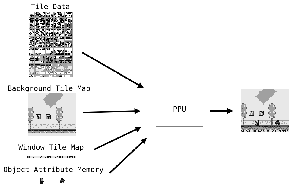
On the Gameboy, a render is composed of multiple layers that the PPU assembles to form the image that’s displayed on screen.
These layers consist of:
- Background layer: As its name implies, this layer contains the pixels that are part of the background.
- Window layer: This layer is drawn on top of the background and is similar to the background layer, with the exception that it may not fill the entire screen. This layer is often used to implement UI elements.
- Object layer: Objects (also called sprites) are the top layer and are usually used for dynamic objects that can move in a scene, such as characters, enemies, items, and so on.
From the CPU standpoint, each of these layers corresponds to a buffer mapped in video memory. When the game wants to render, it just fills these buffers, sets up some MMIO registers, and the PPU will then use all this to render a frame and send it to the LCD.
Tile Data
All of these layers are composed of so-called tiles. A tile is an 8x8-pixel square that can be specified in memory. Tile data are stored contiguously in a memory region and are indexed by a tile map. These tiles are encoded with 2 bits per pixel (meaning a single tile fits in 16 bytes), where each pixel value is an index to a 4-entry color LUT that can be configured through MMIO registers.
Tile Maps (Background / Window)
This buffer contains a list of indices that map a tile on screen to a tile in the tile data area.
Objects
Objects are stored in a so-called OAM (Object Attribute Memory) region. The OAM contains 40 entries, where each entry specifies the X/Y coordinates of the object, the tile index from the tile data region, and some attributes that affect rendering. As you can see, the fact that objects use x and y coordinates instead of a screen tile to tile data mapping makes these more suited for dynamic objects since the game can simply update the object coordinates.

The PPU State Machine
An important aspect to understand the PPU mode of operation is the fact that it works in scanlines. What this means is that the PPU outputs pixels to the LCD line by line, and thus the state machine reflects that.
When drawing a frame, the PPU goes through four different modes:
- OAM search: In this mode, the PPU will walk through the OAM table and search for all the sprites that are displayed on the current line.
- Pixel transfer: Once OAM search is done, the PPU will actually transfer the pixels of the current line, row by row, to the LCD.
- Horizontal Blank: The PPU goes to this mode when all the pixels from the current line have been shifted to the LCD. At this point, the PPU idles until the start of the next line.
- Vertical blank: The PPU goes to this mode when all the 144 lines have been processed and idles until the start of the next frame.
The Pixel FIFOs
During pixel transfer, to output a pixel to the LCD, the PPU internally uses two pixel FIFOs: a background FIFO for windows and backgrounds and a sprite FIFO for objects. The output of both FIFOs then goes through a pixel mixer that decides which pixel has higher priority and should be drawn based on some attributes of the current OAM entry.

Nintendo 64 (5th generation, 1996)
The Nintendo 64 is the first 3D console released by Nintendo.
From 2D to 3D
Switching from 2D to 3D implicates very different design decisions. This time, instead of having just layers, we are now working with 3D models that consist of lower-level primitives such as triangles and rectangles. For ease of use, these primitives are represented by their 3 or 4 points (called vertices) that each contain a list of attributes (typically position, color, normal vector, texture coordinate, etc.). And with this kind of data, it is up to the hardware to create an image. As you may already know, rendering a 3D scene given just vertices requires at least two parts:
- Vertex transformation: projecting scene space coordinates from each vertex to screen space coordinates. This usually consists of a matrix multiplication between each vertex and a projection/view/model matrix.
- Rasterization: converting vertices into pixels on the screen. This part is a bit more complicated and has multiple steps. Without going too much into details, these steps usually consist of:
- A scanline conversion step to determine which pixel is covered by the current primitive line by line. It’s after this step that we can start to process pixels one by one.
- A depth test that checks whether there is another pixel that’s supposed to be in front of the one that we’re currently processing.
- Attribute interpolation, which computes the interpolated values from each pixel within the primitive (remember that we only have attribute values from each of the vertices of our primitive; we still need to compute the values between the vertices). The interpolated values are then used for color blending, shading, texture mapping, etc.
Now that we have a better understanding of the differences between 2D and 3D graphics processing, let’s see how it’s done on the Nintendo 64.
The Nintendo 64 “GPU”
First, let’s look at the different components of the Nintendo 64. The two main chips inside the Nintendo 64 are the main CPU and the RCP (Reality Co-Processor). The main CPU is a MIPS R4300-based CPU where the main code of the game runs, and the RCP is a component designed by Silicon Graphics that actually contains two chips:
- The RDP (Reality Display Processor). This chip is the actual hardware rasterizer that takes transformed vertices, shading and texture attributes, etc., and turns them into pixels on the screen.
- The RSP (Reality Signal Processor). This chip is a general-purpose CPU that can be programmed to run tasks in parallel with the main CPU. It is notably used to perform the vertex processing part of the graphics pipeline.
As you can see, the Nintendo 64 has a hardware rasterizer but no dedicated unit for vertex transformations. This means that this part has to be implemented in software, but fortunately, this is the kind of task the RSP can do well thanks to its SIMD instructions, and we don’t have to waste precious CPU cycles.
So how do these components interact with each other?

- First, the CPU needs to program the RSP for vertex transformation. It does so by sending a task that contains the appropriate microcode as well as a so-called “display list”. This display list is a list of rendering commands that make up the graphics API.
- Then, the RSP processes the display list sent by the CPU and emits a lower-level display list format to the RDP that contains rasterization commands.
- Finally, the RDP processes the rasterization commands and writes the pixel values back to the frame buffer, which is used by the video interface to display the rendered image on screen.
RSP
The RSP is a general-purpose, custom MIPS-based CPU with added SIMD capabilities. It can be programmed with what’s referred to as “microcodes” and can be used by the CPU to delegate various tasks that could benefit from SIMD capability. Having such a multi-purpose chip allows lots of various computations to be performed by the same hardware resources, effectively saving up on silicon at the cost of having to schedule tasks efficiently. This chip is commonly used for tasks such as JPEG decoding, audio mixing/ADPCM decompression, and more. But what we’re interested in here is graphics processing.
In the context of graphics processing, there are actually multiple microcode variants that can have more or fewer features and that depend on the game. However, even though this part could be completely customized for each game, there are actually only a few different variants, and a lot of games end up using the same microcode variants provided by Nintendo.
As previously said, the task of the graphics microcode is decoding the display list commands sent by the CPU and issuing rasterization commands to the RDP.
These display list commands are microcode-dependent and usually describe textures, light sources, matrices, input primitives (triangles and rectangles), and rendering modes/options. As an example you can find here, the list of commands supported by “F3DZEX2” (Fast 3D Zelda Extended 2: the microcode used by Zelda games).
In order to generate rasterization commands, the graphics microcode has to perform vertex transformation, backface culling, clip testing, and lighting calculations.

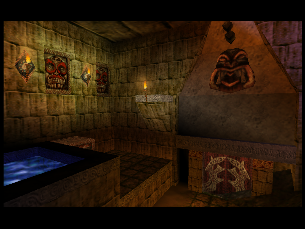
Indiana Jones and the Infernal Machine is one of the rare games where the developers put their hands to work and wrote their own RSP microcode, allowing them to push the N64 to its limit for their own needs. Notice the care that went into the lighting in the room. You can read more about it here.
RDP
The RDP’s task is to perform the final rasterization based on another display list format. During this rasterization stage, the RDP does scanline conversion, scissoring (essentially the same thing as clipping but for pixels), attribute interpolation, depth comparisons against the Z-Buffer, antialiasing, texture mapping, color combining, and blending with the frame buffer.
The display list format decoded by the RDP (you can find all the commands here) contains commands to set internal registers, rendering mode, information about textures, and primitives to render.
If you look more closely at the actual drawing commands, you may notice that the parameters are a bit weird. The reason for that is that the RDP was likely subject to a tight transistor budget. And accordingly, it is rather simple and expects rendering commands’ parameters to be pre-processed (most of which is being done in the RSP), which is usually different from the sort of data you would manipulate in a game engine, so that it has as little work to do as possible.
To name a few examples, since floating-point numbers are expensive, and although the main CPU has an FPU, the RSP and RDP don’t support IEEE-754 and instead use a fixed-point format to represent numbers with a fractional part (such as vertex positions or texture coordinates).
Additionally, triangles in the RDP display list format aren’t represented by the attributes of each of their vertices but by a more complicated format that describes inverse edge slopes, starting values, and attribute partial derivatives by x and y. (You can read all the math behind it here). These parameters may seem complicated at first sight, but they actually make attribute interpolation and scanline conversion very easy to compute with an “edge walking” algorithm without any preliminary step.
Color Blending / Combining
During rasterization, each pixel goes through two RDP sub-units in order to get its final color: the color combiner and the blender.
Both units have a fixed equation with programmable parameters.
Color Combiner equation:
- $(A - B) \times C + D$
Where the input parameters can be configured to textures (up to two textures are supported), color registers, noise, computed shade, primitive color, etc.
Blender equation:
- $\frac{a \times p + b \times m}{a + b}$
Where the input parameters can be configured to the framebuffer, fog/blend color registers, and constants.
The full pipeline

- RS (Rasterizer): Performs edge walking, scissoring, and attribute interpolation.
- TX (Texturizing Unit): Samples textures from texture memory (4 texels per pixel).
- TF (Texture Filter): Takes the 4 input texture samples and performs a filtering algorithm (can be configured to do point sampling, box filtering, or bilinear interpolation).
- CC (Color Combiner): See explanation above.
- BL (Color Blender): See explanation above.
GameCube / Wii (6th/7th generation, 2001 / 2006)
In terms of graphics, the Wii and the GameCube essentially have the same GPU designed by ATI (now AMD), the only difference being that the Wii’s GPU (called Hollywood) runs at a higher clock speed than the GameCube’s (called Flipper).
Now, if we compare to the Nintendo 64, the first big difference is that this time, graphics processing isn’t separated into two parts like it was with the RSP and RDP in the Nintendo 64. What we have instead is a single chip that processes the command list issued by the CPU and dispatches the commands to their respective sub-units. This design makes programming for the GPU much easier since the programmer doesn’t have to implement part of the rendering through a microcode system like with the RSP.
If we were to ponder the semantics a bit, this technically means that the vertex transformation stage switched from being fully programmable to being fixed, thus offering fewer possibilities in theory. In practice, however, game developers seldom programmed their own RSP microcode, and the existing ones are expecting a fixed format for vertex attributes. So although the Nintendo 64 does technically allow for the creation of a concept analogous to geometry shaders (a concept in later GPUs that allows a user to generate vertices from the GPU), I am not aware of any graphic microcode that does more than converting RSP primitives into low-level RDP primitives.
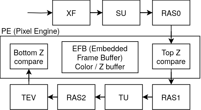
Regarding how vertex transformation works on the GameCube, the GPU has a dedicated unit (XF unit) that simply takes a projection and a view matrix through its registers and uses these to compute the screen space coordinates for each vertex.
Towards Fully Programmable Pixel Processing
One of the big improvements in the graphics API design is the TEV (Texture Environment) unit. This unit adds much more flexibility when programming the shading process.
Whereas the RDP only allows tweaking some variables in a pre-defined equation, the TEV unit allows programmers to make their own pixel color equation. The way this TEV unit works is by exposing 16 programmable stages, where each stage can have four inputs, an operation on these inputs, and one output. The fact that this works in stages means that these stages can be chained together to create much more complicated operations when shading a pixel (up to $5.64\times10^{511}$ possibilities). The TEV unit almost works like a processor where each stage would be an instruction, but very limited.
The operation on each stage can be one of these:
GX_TEV_ADD: $tevregid = (d + lerp(a, b, c) + tevbias) \times tevscale$GX_TEV_SUB: $tevregid = (d - lerp(a, b, c) + tevbias) \times tevscale$GX_TEV_COMP_R8_GT: $tevregid = d + (a.r > b.r \text{ ? } c : 0)$GX_TEV_COMP_R8_EQ: $tevregid = d + (a.r == b.r \text{ ? } c : 0)$GX_TEV_COMP_GR16_GT: $tevregid = d + (a.gr > b.gr \text{ ? } c : 0)$GX_TEV_COMP_GR16_EQ: $tevregid = d + (a.gr == b.gr \text{ ? } c : 0)$GX_TEV_COMP_RGB24_GT: $tevregid = d + (a.rgb > b.rgb \text{ ? } c : 0)$GX_TEV_COMP_RGB24_EQ: $tevregid = d + (a.rgb == b.rgb \text{ ? } c : 0)$
Where a/b/c/d are the input colors (can be either the output from the previous stage, a texture, a color register, a constant, or the computed shade), tevregid is the output register, tevbias/tevscale are configurable scales and biases, and lerp is the linear interpolation function $lerp(v0, v1, t) = v0 \times (1 - t) + v1 \times t$.
As you can see, the TEV unit is not as complex as “shaders” on modern GPUs yet (i.e., general-purpose turing complete programs executed on the GPU), but it still offers much more capabilities than the Nintendo 64. It’s difficult to draw a line between what’s a fixed-function pipeline and what isn’t, since one could argue that the Nintendo 64 already isn’t a fixed-function pipeline because of the way you can set up the blender / color combiner equation parameters. But with the TEV unit, we’re definitely moving towards fully programmable pixel processing.

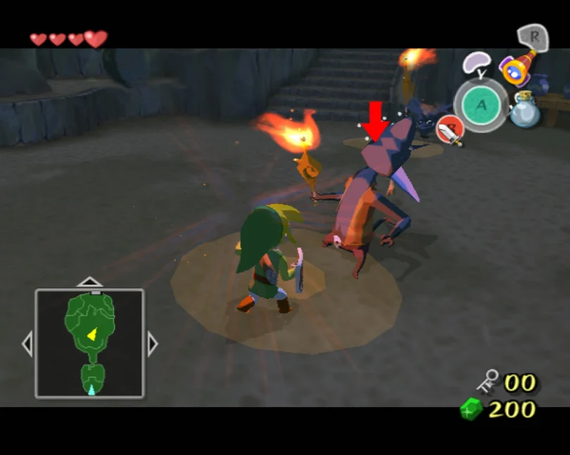
The Wind Waker is notably utilizing the TEV unit to achieve its characteristic toon effect as well as a myriad of other tricks to make the environment affect the rendering. Some of which are explained in this video.
Programmer Interface
From the programmer’s perspective, the GPU exposes a memory-mapped FIFO register that’s used to issue commands. These commands can be either rendering commands to perform draw calls or commands to set the internal register for each accessible unit (e.g., to load the projection matrix in the XF unit, configure the TEV stages, etc.).
The full pipeline

Do note that apart from the XF and TEV units, other components are not documented, and thus the below descriptions are based on my interpretation of the unit names and therefore are to be taken with a grain of salt.
- XF (Transform Unit): Performs vertex transformation on input vertices with user-specified matrices.
- SU (Setup Unit): Supposedly performs setup operations on vertices for the rasterization (e.g., computing barycentric coordinate conversion coefficients) as well as clipping and culling.
- RAS0 (Edge/Z-Rasterizer): Supposedly does scanline conversion and computes interpolated Z values.
- Top Z-Compare: Performs Z testing with the interpolated Z values.
- RAS1 (Texture Coordinate Rasterizer): Computes interpolated texture coordinates.
- TU (Texture Unit): applies textures from input texture coordinates.
- RAS2 (Color Rasterizer): Computes interpolated colors.
- TEV (Texture Environment Unit). Applies TEV stages (as explained earlier) in order to compute the pixel’s final value.
- Bottom Z-Compare: Performs late Z testing. This is because the GameCube supports Z-textures that are applied during the TEV stage and can offset the Z coordinate of the current pixel.
Closing remarks
In this first part, I discussed the earlier GPU architectures, where everything was still very graphics-oriented with a lot of fixed-function stages.
In the next part, we will start to see the base of modern GPUs and the concept that turned GPUs from simply graphics accelerators to general-purpose computing hardware: the unified shader model.
Glossary
MMIO (Memory-mapped IO)
A function exposed by the hardware to the memory interface. Typically, for exposing hardware registers to the CPU.
Read more here.
Rasterization
The concept of transforming primitives in vector format into pixels on a screen.
More on Wikipedia
Projection/View/Model Matrix
- Projection Matrix: A matrix that projects points in camera space to screen coordinates.
- View Matrix: A matrix that transforms points in world space to camera space.
- Model Matrix: A matrix that transforms points in model space to world space.
You can read more about these here.
Depth testing
Before a pixel can be written to the framebuffer, the GPU has to make sure that there is no pixel “in front” of the current pixel. A depth test refers to this check. The most widespread technique for depth testing is through the usage of a Z-Buffer. This special frame buffer, similarly to the color buffer, stores information about each pixel on the screen. Only, instead of storing the pixel color values, the Z-Buffer stores the pixel depth (in other words, the Z coordinate) value.
You can read more about it here and here.
Shading
Shading usually refers to lighting calculations on an object based on its material and light sources.
More here.
Texture Mapping
The concept of applying a texture to a surface. Usually, each vertex of the surface will have texture coordinates in its attributes so that the texture unit knows where to sample pixels from within the texture.
More here.
MIPS
MIPS is a computer architecture of the RISC family.
More here.
SIMD
In the context of computer architecture, SIMD (Single Instruction, Multiple Data) instructions are instructions that can compute an operation on a vector rather than on a single value.
More here.
Backface Culling
Backface culling is the process of getting rid of primitives not facing the camera. The basic principle lies on the assumption that when a primitive is not facing the camera, it usually means that it’s at the back of a model and thus is masked by the front of the model. Discarding such primitives reduces the number of polygons the GPU has to process, which results in performance improvements.
More here.
Clipping
Clip testing checks for primitives outside the view frustum and discards them.
More here.
Antialiasing
During the rasterization stages, the conversion from a continuous space to a discrete one can generate “jagged” edges. Antialiasing techniques aim to correct this effect. A common way of doing so is by sampling more pixels than required and applying a filtering algorithm based on subpixel coordinates.
More here.
FPU
A floating-point unit is a hardware unit that can perform operations on floating-point values.
More here.
Fixed-point
Fixed-point is a means of representing numbers with a fractional part by separating the integer and fractional parts of the value with a fixed number of bits. Fixed-point representations are often used on limited hardware due to their inexpensive nature compared to floating-point representations such as IEEE-754.
More here.
Barycentric Coordinates
A coordinate system that essentially says how far a point is from each vertex of its containing primitive. During rasterization, the attribute interpolation step requires going through such a coordinate system to be able to compute the intermediate values.
More here.
References and Further Reading
General
- A trip through the Graphics Pipeline 2011. A must read for anyone interested in modern GPU architecture.