Prerequisite
To understand this tutorial, you will need some prerequisites :
- Little bit knowledge on matrices computation
- Basic command line using your preferred Terminal (Powershell in my case)
- C/C++ embedded programming
- STM32 programming and toolchain
Introduction
In this tutorial we will implement a really simple I2C communication with an IMUs (Inertial Measurement Unit) and program an Kalman Filter to filter out the data in order to get the attitude (orientation) of our sensor. It is used in spacecraft attitude control.
Stuff Needed
For doing the same exercise, you will need :
-
An MCU, I will use ‘Black Pill V1.2’ using an STM32F401CCU6. You can use any mcu, an STM32 is better to be able to follow the I2C communication part. Since we will use a lot of floating point math, an mcu with FPU (Floating Point Unit) is way better. (STM32F4 has one).
-
ST-Link and an TTL to program/debug the mcu and recover telemetry from the mcu.
-
An IMU, I will use an MPU6050, same as any IMU will do the job, but you will need to adapt the I2C communication part.
A good list of STM32 dev board.
Configuration / Build
To be able to build you will need at least these programs:
-
- With the extention Teleplot To visualize data
-
On Windows
-
For Linux you will need to find the package name related to your installation (see a link here):
- package arm-none-eabi-gcc
- package stlink
- package make
Explanation of terms
IMUs
An IMUs (Inertial Measurement Unit) is a sensor that measures the body’s applied force, rotation rate and orientation. It’s a major component in all attitude control systems (aircraft, rockets, missiles).
The one we will use is a MEMS (Micro-ElectroMechanical Systems),they are microscopic devices that use the same production mechanism as semiconductors. Those sensor are smartphone grade thus small, light and low power consumption. They still have sufficient accuracy for every day product.
The MPU6050 is a 6 DOF (Degrees of freedom) sensor. For each axis on our body (X, Y, Z) we have an Accelerometer (force on this axis) and a Gyroscope (rotation rate on this axis). You can see that none of those sensors (Accelerometer and Gyroscope) provide the orientation of our body.
Kalman Filters / Sensor fusion
To be able to get an orientation angle correctly with good accuracy, we need to use a sensor fusion algorithm. It’s a process of combining sensor data or data derived from disparate sources.
Here we are going to estimate the orientation with the gyroscope and the accelerometer. The accelerometer data can be used to look where the earth gravity vector is and be able to get an estimation of the orientation. We can really use those sensor separately,
- Accelerometers are very sensitive to vibration
- Integration of the signal of the gyroscope leads to an ever increasing error This allows the use of both advantages: Accelerometer for long-term correction of our orientation and gyroscope for short-term correction.
One of the most popular filters is the Kalman Filter. This filter has two steps : prediction, and correction.
Prediction Step
The filter predicts the current state based on the last estimation. The prediction step is used when we have a sensor that doesn’t get refreshed often enough. The algorithm is still able to predict steps if we want a faster loop than the sensor is able to give us. For example GPS tend to have a very slow refresh rate.
Example
If we want to predict the roll of an airplane. To make the prediction we use the old roll angle known and we can use the roll angle (previously measured) to adjust the new roll prediction. \text{Roll}(t) = \text{Roll}(t - 1) + \text{RollRate}(t - 1) \cdot \Delta T
Correction Step
This step is called every time new sensor data. With the last estimation, the confidence in this prediction and with noise values (stored as matrices) it will correct the new sensor data. Sensor has noise and this step gets the new data and limits the noise to the prediction.
Implementation
STM32CubeMx configuration
So I will use an MPU6050 from InvenSense, on a dev-board: GY-521.
It uses I2C communication. We will use 100 KHz (I2C Standard-Mode) for simplicity.
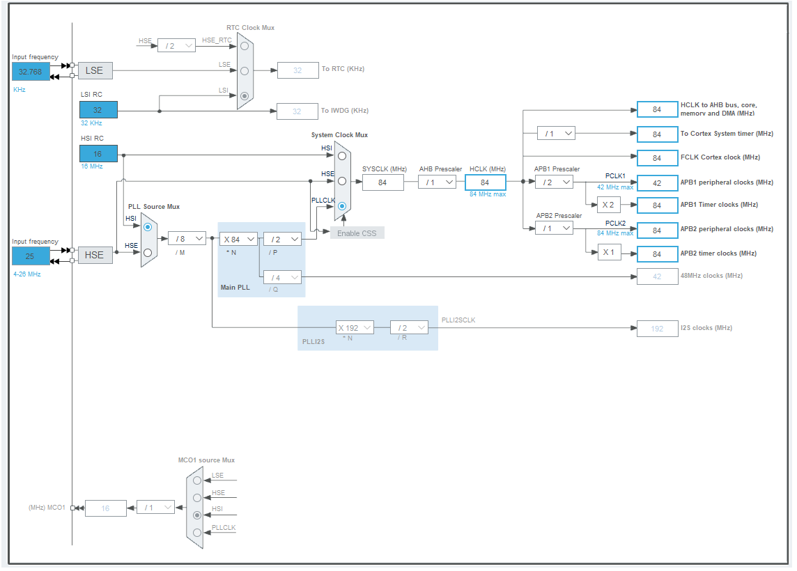
- Enable RCC Ossilator (Crystal/Ceramic Ossilator) in Pinout and Configuration / System Core / RCC

- Set the crystal at the right speed in the clock configuration menu. And set the max speed for the HCLK clock (The one in the middle) in my case it is
84 MHz
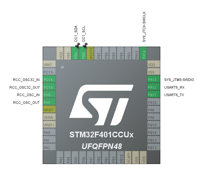
- Finally in Pinout and Configuration, enable :
- I2C used by your MPU6050 (my is on I2C1 with pins PB8; PB9)
- UART for telemetry output (my is on UART6 with pins PA11; PA12)
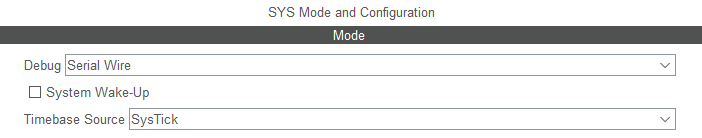
- In System Core / SYS enable Debug: Serial Wire if you use an ST-Link for debugging
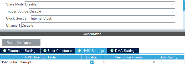
- For the Kalman Filter we need a proper delta time, even though it is possible to have a non constant delta time, we will use a timer to get a known and stable delta time. So Enable any General purpose timer, like TIM2 and enable global interrupt of this one.
- We will refresh the sensor at
100Hzto do this we need to setup the timer. - Use a
PrescalerofHCLK - 1. HCLK id the value you set before in Clock Configuration. (In that case you end up on a 1 MHz Timer) - Use a
Counter Periodof10000 - 1. 1MHz divided by10'000is100Hz
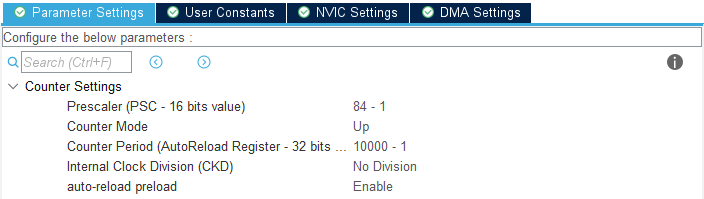
You should end up with something like this:
In Project Manager / Project, select Makefile to used it with command line.
Build setup
The first step is to end setting up the toolchain. This project will use C++ and Eigen (for Math).
Adding Eigen
Eigen is a C++ Math library. You can either clone it or if you are working on a git repository, use git submodule. I will go for the latter but here are the two variants. You need to be in the working directory of the project
- Cloning the repository
git clone git@github.com:libigl/eigen.git Eigen - Add as a submodule
git submodule add git@github.com:libigl/eigen.git EigenWarning: Here I am using the repository of Eigen on github but the real on is on gitlab (see Eigen on gitlab). The github version hasn’t been maintained for 3 years but since it is more popular to have a github account, I use the github one, it is way enough for the little math we will use. (Prefer using the gitlab on with real project thought)
Makefile Modification
Since we will use C++ (to get Eigen working) we will need to change our generated Makefile.
Create a .cpp file in Core/src, in my case MPU6050_Kalman.cpp.
In the Makefile :
- After
C_SOURCESaddCPP_SOURCES = Core/Src/MPU6050_Kalman.cppto add our file to the compiled objects - In binaries sections add
CPP = $(PREFIX)g++underCC = $(PREFIX)gccto add the cpp compiler path - In
C_INCLUDESadd the path to Eigen-IEigen - To remove warning from Eigen on our cpp file, add after
CFLAGS
|
|
- Since I going to use Teleplot to draw graph, I need to print floating point, which isn’t supported by default, so add to
LDFLAGS:-u _printf_float - In
list of objectsadd the support to our cpp file
|
|
-
Finally since we will have cpp compiled objects files, change the assembly compiler from gcc to g++. In the
$(TARGET).elfrule, change$(CC)by$(CPP) -
Last one, to be able to flash our card easely you can add the
flashrule (You will need to check the upload address of your MCU configuration thought, it should be ok if you are using the one by default):
|
|
Interact with the IMU
Now you should be able to compile the project.
Last step before implementing the I2C communication and the Kalman Filter. In order to get printf working, we have to define _write.
Using the UART defined in CubeMX (for my case huart6), we have:
|
|
Interacting with the IMU
Following the product specification and the register map, we can set up the MPU6050.
Setup the device
So in USER CODE 2 in main.c we can write our code
|
|
Receiving Data
As described earlier, we are going to read the sensor at 100Hz using a timer interrupt. So first thing first we need to launch the interrupt callback. Under the code we just add, launch the timer interrupt callback. By the way, I have used TIM2.
|
|
Each our timer overflow a callback is called, so let’s define this function
|
|
The MPU always sends data as a 16 bits signed integer, unchanged from the select range we’ve set up earlier. To do the conversion, we will use two defines
|
|
To get all data at the same time we need to use an struct according to the data send
|
|
For each value there are 2 bytes, the first is the MSB(Most Significant Bit) and the second is the LSB(Least Significant Bit), we will need to regroup them later. Also, the MPU is able to return the temperature, because it’s gyroscope and accelerometer are sensitive to temperature. We won’t use it here, as this will have almost zero impact on our data.
Now we can read this data and print them through the serial port. I am using the Teleplot convention to get Teleplot working with my data.
|
|
Using Teleplot, we can now see our Accelerometer and Gyroscope data. I have save my Teleplot layout, you can import it from my github in .vscode/teleplot_layout.json
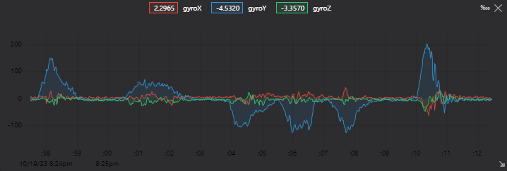
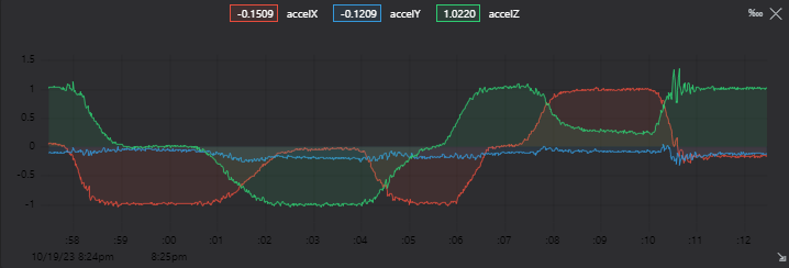
As you can see measures are really noisy, almost unusable data for a controller from the gyro.
Kalman Filter
So here we are going to set up our very simple Kalman Filter. This example is not a great example of a complete Kalman Filter, I have removed some components that aren’t needed in our simple case. If you want more information, and the full equation for a Kalman Filter, you can check out readthedocs website.
Just before declaration of all our Kalman components, we will need to variable, the delta between each step and a conversion from radian to degree
|
|
And with the last one, we are able to recover the orientation from the accelerometer.
|
|
We can do that because at any instant earth is pulling our sensor toward the earth center at 1G so if the sensor is mostly static we can use an accelerometer to calculate the orientation relative to the earth. Again this won’t work in a device with force applied to it, since earth gravity will be non-distinguishable. In that case an IMU with a magnetometer is better since it will get orientation from the earth’s magnetic field. But our MPU6050 doesn’t have one.
For simplicity we will handle only roll and roll_rate in our kalman filter, but you can add all the component you want, just need to adapt the size of the differents matricies and vectors.
So let explain breifly Kalman Filter equations. First with it’s components:
X: A Vector2, storing [ roll; roll_rate ]P: A Matrix2*2, Witch is the “confidence” in the predictionF: A Matrix2*2, This one is const, and store the Model of our system. In instance, it will be this matrice that store the fact that roll depend on roll and roll_rate.QandR: Are both Matrix2*2, There are const. They need to be tune to select whether the sytem is more “confident” to the prediction or more to the actual measurment.Qis how “not confident”(noise) we are on our prediction, andRstore how “not confident”(noise) we are on our measurment.
So let’s define them:
|
|
I won’t explain how math behind this works, you can check readthedocs website to get the full equations.
The first things need to do is get the actual mesurment under the Kalman component z it is a Vector2 containing [roll; roll_rate].
|
|
|
|
With the Kalman filter we now obtain a smoother roll and roll_rate which could now be used in a PID controller for exemple, or any type of controller, which are often very sensitive to noise and act terribly with vibration.
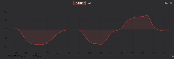
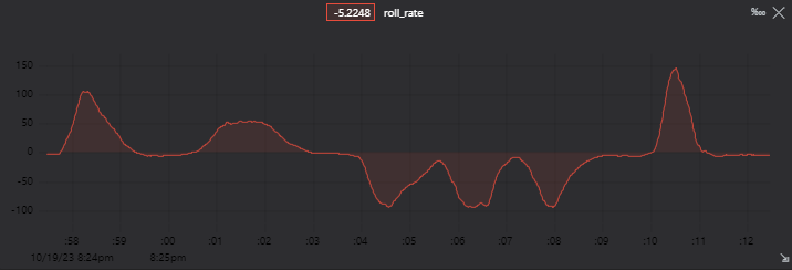
And this give us, for the roll measurement:
- In red the Kalman Filter roll output
- In Blue the gyroscope value (GyroY)
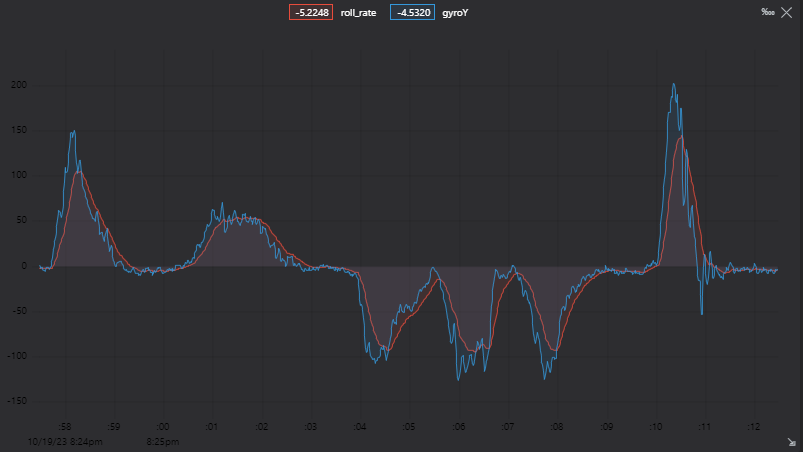
But You can see a problems of filters in general: lag. Which can be reduced by:
- Tuning correctly matrices
QandR. - Having a better model matrice
F. - With a complete Kalman Filter.
Conclusion
In this text, we have set up communication with an IMU (Inertial Measurement Unit), which is a sensor that we can use to compute the attitude (orientation) of a body. And to compute this attitude correctly, we used a simplified Kalman Filter. It is a sensor fusion algorithm that combines data from different sensors (in our case, an accelerometer and a gyroscope) to filter out to a usable signal.
As said earlier the Kalman Filter used here is a simplified version (it doesn’t have the Q and R matrices.).
So if you want to go further checkout readthedocs.
Projects Files
You can find every files on my github.
Sources
MPU6050: product specs MPU6050: register map
readthedocs: Kalman Filter equations
Wikipedia: IMU Wikipedia: MEMS