Introduction
Microcontrollers are the backbone of countless embedded systems, ranging from consumer electronics to industrial automation and medical devices. Each architecture brings its unique capabilities tailored to specific application needs. However, developing, testing, and analyzing firmware across diverse architectures presents significant challenges: Physical hardware is often not accessible, and testing directly on target devices can be risky and inefficient, especially when handling sensitive or high-risk systems. This highlights the need for emulation.
In the previous article, we delved into the critical role of parsing firmware formats, which can often require reverse-engineering proprietary or obscure structures, as well as the intricacies of memory layouts and base addresses. While these topics underscored the challenges of creating a generic emulator, they were just the beginning. In this article, we’ll build on that foundation to examine how to determine entry points after establishing base addresses, and analyze how Instruction Set Architecture differences impact program control flow, with insights from QEMU’s source code.
Before diving in, readers should have read the first part of the Pre-Emulation series, and have a foundational understanding of emulators, microcontroller architectures, and firmwares. This knowledge will enhance comprehension of the methodologies and challenges discussed in this article.
Note: Code segments provided in this article are adapted for clarity and are not 100% accurate. Always check out the actual source code!
Instruction Set Architecture
As you all know, an Instruction Set Architecture (ISA) defines how software controls hardware at the processor level. While we, developers, rarely write assembly code directly, understanding the ISA is crucial for optimizing code, debugging, and tasks like boot software and low-level kernel development.
It is necessary, before testing, to determine what ISA the firmware uses, so that the emulator can disassemble the firmware into the correct machine instructions, endianness (little- or big-endian), and word-size. In addition to determining the ISA family (ARM, x86, MIPS, ARM64, AVR, etc.), the ISA version is needed to correctly disassemble instructions. For example, is it ARM with Thumb support and floating point instructions or not?
Our main tool here, QEMU, is an instruction-accurate emulator, which means that it emulates different ISAs through instruction-level translation, supporting full-system emulation for rapid prototyping and system-level exploration. Some tools can, when given a firmware, determine the ISA by itself, like Binwalk which attempts disassembly across multiple ISAs, flagging an ISA as a strong candidate if it successfully disassembles more than a specified number of consecutive instructions (500 by default). However, QEMU does not determine firmware ISA automatically: Each ISA of every emulated architecture is already in code. The user needs to specify correct architecture and options himself. Basically, QEMU differentiates between A32, AArch64 and Thumb when loading ARM firmware based on what CPU the user has chosen (Cortex-A15, Cortex-M3 …).
Now let’s talk about the main differences between each architecture’s instruction set:
ARM
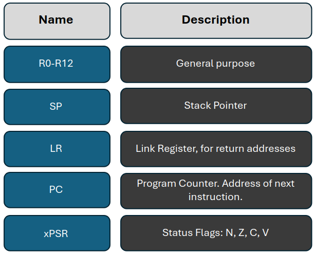
ARM Architecture supports multiple instruction sets, particularly in the newer ARMv8-A models, which include A32 (ARM), T32 (Thumb), and A64 (AArch64). These instruction sets are based on a load-store architecture, where all operations occur between registers, with memory accessed via dedicated load and store instructions. This design is optimized for speed and efficiency, utilizing powerful auto-indexing addressing modes and a dense instruction set like Thumb for higher code density. Its RISC-like simplicity aids in rapid execution—most instructions complete in a single cycle, and conditional execution of instructions further enhances performance.
AVR
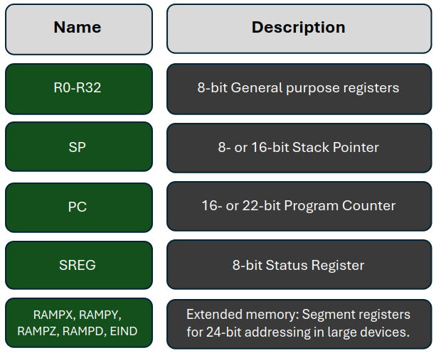
AVR’s ISA is a simple 8-bit RISC architecture initially designed for low-power, low-cost applications. Unlike ARM’s flexible and scalable architecture, its ISA is constrained, but this simplicity makes it well-suited for emulation. Most AVR instructions complete in a single cycle, and their reliance on register-based operations makes them highly predictable for emulation. AVR’s memory-mapped I/O ports, however, pose unique challenges, as peripheral behavior needs to be carefully replicated in the emulation environment to ensure correct functionality. QEMU handles this by mapping these ports directly into the memory space, enabling seamless control of AVR’s peripherals during emulation.
Microchip’s architectures: PIC
PIC Architecture features bit manipulation, skip instructions, and shadow registers for interrupt handling, making it highly optimized for embedded control tasks. However, its ISA is more complex and varied than both ARM and AVR, featuring different instruction formats across its family of MCUs. Among them are:
- PIC16, which uses an 8-bit RISC architecture with a simple instruction set.
- PIC32, based on MIPS32, has a completely different architecture.
- PIC64, announced in July 2024, based on RISC-V, yet another ISA. Microchip selected RISC-V for the PIC64 series to allow modular customization, ensuring compatibility with existing SoC architectures and providing enhanced security and time-sensitive networking for diverse applications, mainly for the aerospace and defense market.
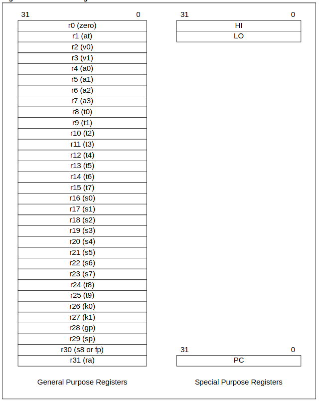
As we said, PIC32 follows MIPS32 Release 2 ISA. It uses three primary instruction formats:
- Immediate (I-type) include an opcode, a source operand, a destination operand, and a 16-bit signed immediate value for various operations.
- Jump (J-type) that feature a 26-bit relative instruction offset for jump destinations.
- Register (R-type), where three operands are used—two source registers and one destination register—allowing for efficient register-based operations.
So, is PIC really that complex to emulate because of this ? Well, no, because it has already been done in multiple projects and tools, such as this QEMU fork by Serge Vakulenko which emulates PIC32 only, as well as PicSim, done from scratch. My guess is that Microchip’s diverse architecture choices make it hard to implement one generalized emulator for all of them. Supporting PIC16, PIC32, and PIC64 would require separate emulation engines due to their architectural differences.
While the PIC ISA is not inherently more complex than others, its variation across versions, less demand in the open-source community, and specialized hardware peripheral support make it less attractive for QEMU to emulate. There are already established tools for PIC, making the development effort for QEMU less of a priority.
Determining processor
I won’t go too deep into this section, as it really depends on the fidelity of the emulator you’re using, but it’s worth mentioning! For some emulators, identifying the exact processor might be absolutely necessary. QEMU, our main example, is instruction-accurate and does not need such level of emulation fidelity, so the user has to manually specify which processor to emulate. But with cycle-accurate emulators like gem5, it’s a whole different ball game. You’ll need to know the exact processor since the same ISA instruction can be implemented differently at the cycle level depending on the processor.
This challenge ties directly to determining the memory layout and ISA. The only real solution here is to read the documentation (yes, all of it). If you don’t have access to the actual hardware, you’re stuck with aggressive instruction-finding and analyzing how those instructions interact with memory, to then compare that analysis against known processors to narrow down options. It’s a tedious and error-prone process, and honestly, this is probably why you don’t see it done very often. Pain, not enough gain!
Determining Entry Point
Now that we’ve covered memory layout and base address, let’s discuss how to determine the firmware’s entry point.
The entry point in microcontroller emulation is pivotal: It marks the initial instruction executed after a reset or boot-up, where initialization sequences start, critical system registers are configured, and program flow commences. This information may be embedded in the binary itself. For instance, Executable and Linkable Format (ELF) files specify the entry point within their metadata (try running readelf -h <FILE>.elf in your terminal!). Alternatively, various analyses can be performed to provide entry point suggestions to assist the practitioner, but again, this is not QEMU’s case.
When loading an ELF file, QEMU relies on load_elf_<SZ>(), which is called in the architecture-specific file located at hw/<MCU>/boot.c.
|
|
As we discussed earlier, In ARM Cortex-M systems, the entry point is a single address stored in the ELF header. On boot, the Program Counter (PC) loads this value from the reset vector (often 0x80000000), starting program execution. The ARM setup allows flexibility for custom entry points, though they must be in a root execution region where the load address matches the execution address.
For AVR microcontrollers, QEMU sets the entry point at 0x0000, aligning with the PC reset address:
|
|
Otherwise, if not an ELF, the image is directly loaded image in program memory.
Now, you might wonder, “Why this lack of flexibility for AVR?”. Well QEMU’s choice of 0x0000 as the default entry point isn’t arbitrary, it aligns with the AVR architecture’s convention to start at the lowest address where the PC is reset. In my opinion, flexibility here might be less necessary since 0x0000 is where execution naturally begins. But still, another factor could be that, unlike ARM, AVR PC cannot be directly read. The only way to read out PC is by issuing a RCALL or CALL instruction (depending on the device that support this instruction. For example, RCALL is not supported on ATmega8).
When a RCALL instruction is executed, the current PC is stored onto the stack. If the control is in the subroutine, user can execute two POP instruction to get the PC values (MSB then LSB) in r17. POP will increment SP, so user need to push the SP on the stack again, to be able to do a RET.
RCALL GETPC

GETPC:
POP r16
POP r17
MOV r18, r16
MOV r19, r17
PUSH r17
PUSH r18

RET
Now, let’s talk about PIC. Here again, we’ll focus on PIC32, the most widely used in its family. The PIC32’s base address for the reset vector is straightforward: 0x9D007000. This reset vector is located in boot flash, where Microchip’s compilers place the startup code that eventually jumps to main.
However, if you’re using a bootloader, you’ll likely replace this startup sequence with your own, bypassing the boot flash code and jumping straight to main. Boot flash on PIC32 also contains essentials like the debug vector and configuration words, which may require attention depending on your application.
Loading Firmware
The process of determining base address and loading image is done in the same load_elf() function we covered above:
|
|
The function above iterates over each program header in the ELF file, identifies segments flagged for loading (PT_LOAD) and determines their memory addresses. It calculates a base address by directly from the segment’s physical address or by using a translation function. Throughout, the function tracks the lowest and highest addresses across all segments to establish the memory range needed for the loaded ELF file.
Each architecture has specific conventions regarding base addresses for program start and interrupt handling:
- ARM binaries base addresses typically starts at
0x00000000or0x08000000in ARM Cortex-M devices, marking the flash memory’s beginning with the Interrupt Status Register (ISR) vector and initial instructions. Consistent across ARM but varies by family/model. - AVR’s firmware loads at
0x0000, where the reset and interrupt vectors enable seamless execution from the reset vector. Theload_image_mr()function supports loading raw binary images directly into a specified memory region, beneficial for ROMs targeting unknown device addresses in memory, unlikeload_image_targphys(), which requires a specific physical address. - PIC’s base addresses vary by model. For PIC32, the function
load_image_targphys()would work. This is what is currently done on MIPS microcontrollers.
Disassembly for Control Flow Analysis
In Pre-Emulation, disassembly, initial analysis, and recovering the Control Flow Graph (CFG) are critical steps, even if they aren’t strictly challenges of the phase. Verifying these steps can prevent issues later in the Emulation phase. When multiple entry points exist, like a bootloader, confirming the correct entry point is essential to avoid unnecessary re-hosting.
Let’s take an example for an ARM Cortex-M4 core. This main() sends messages via UART and blink two LEDs when the messages are transmitted using callback functions:
|
|
And here’s the generated CFG, when all previous steps have been completed correctly:

But if I try to load the same main for MIPS64 with a base address of 0x0, we get the following mess, no surprises there.
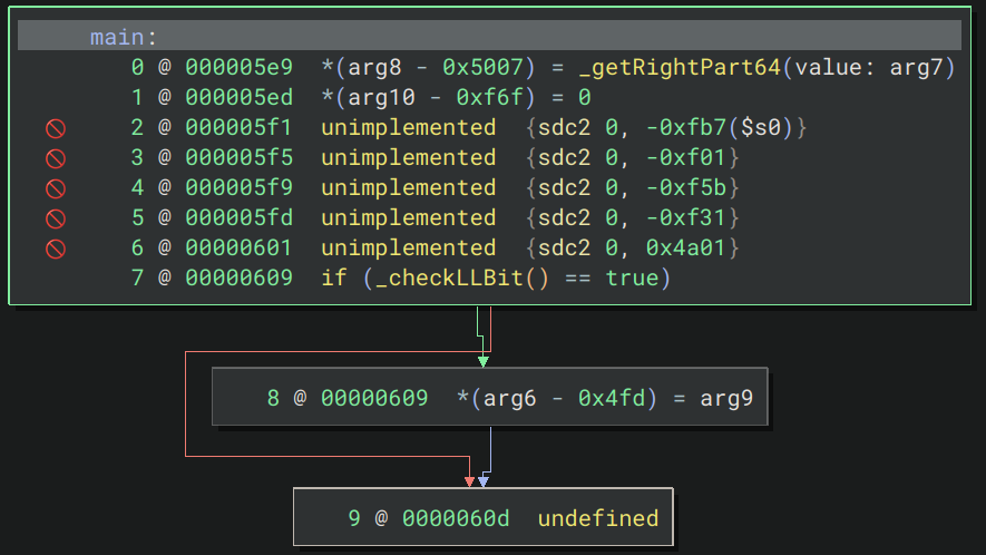
QEMU serves as a primary focus, utilizing C for its disassembly, which allows for robust CFG recovery. However, if control flow passes to co-processors (such as GPUs or DSPs), recovering the CFG becomes problematic. In such cases, practitioners may analyze memory state changes before and after control is handed off, though this can limit emulation fidelity.
When it comes to disassembly, ARM presents a more intricate challenge, with separate files dedicated to each ARM model (32-bit, Thumb modes …etc.). Since instructions can vary in length, QEMU carefully manages how many bytes it reads and processes at each step. In contrast, AVR’s disassembly remains relatively straightforward, primarily dealing with simpler instruction formats, resulting in less complexity within the disassembly logic, as evidenced in target/avr/disas.c.
Ultimately, this disassembly process is performed manually by reading in blocks from memory, setting up the necessary disassembly information, and then iteratively decoding instructions, byte by byte, instruction by instruction, and section by section …
Other emulators, such as angr and Ghidra, also contribute to the landscape of disassembly tools, with angr leveraging Capstone, a disassembly framework for binary analysis, for part of its disassembly process. These tools provide varying approaches to CFG recovery and validation, underscoring the importance of disassembly in the overall emulation workflow. Capstone can also be used in QEMU when disassembling a supported architecture (ARM, AArch64, Mips, MOS65XX, PPC, RISC-V …). This is particularly useful for architectures that have instructions of varying lengths. However, for simpler architectures like AVR, this complexity is unnecessary.
Conclusion
To wrap things up, here’s a quick summary of all the steps involved in the pre-emulation process:
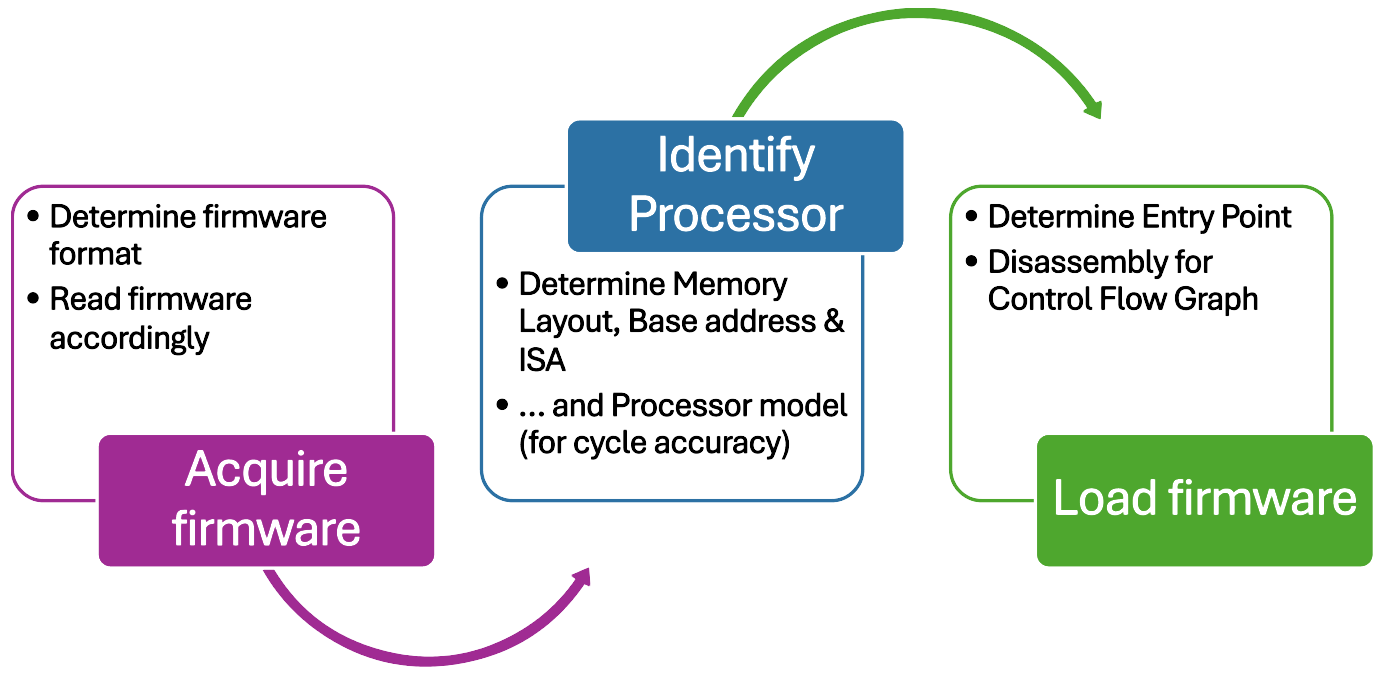
Emulating a microcontroller architecture involves following crucial steps and reading lots (and lots) of datasheets. The complexity multiplies when trying to support multiple architectures with the same tool, often necessitating extensive lines of code to implement even basic features for just one microcontroller among many.
Another factor is the popularity of specific architectures and boards is reflected in the availability of tools dedicated to their emulation. ARM stands out in the open-source community, attracting significant attention from emulation tools, as do x86 and RISC-V architectures. AVR, while simpler due to its straightforward ISA, still presents challenges in emulation, particularly with certain features like EEPROM. PIC, on the other hand, is a case unto itself: Microchip’s own tools dominate the landscape, reflecting the diversity across the family, from PIC16 to the upcoming PIC64, each boasting unique memory layouts and ISAs. In this vast landscape of emulation, if multiple tools fail to meet your needs, it may be worth considering the intricacies of the architecture itself.
Sources
Tools
- Binwalk GitHub Repository: Repository for Binwalk, a tool for analyze, extract and reverse-engineer firmware images.
- Binary Ninja: Official website of Binary Ninja, a binary analysis platform used for reverse engineering.
- angr GirlScout Analysis: Part of the
angrGitHub repository, specifically pointing to theGirlScoutanalysis component for advanced binary analysis. - Firmadyne GitHub Repository: Repository and documentation for Firmadyne, a framework for emulating and analyzing firmware of embedded Linux-based devices.
- QEMU GitHub Repository: The official repository for QEMU, open-source machine emulator and virtualizer.
- gem5: Link to the gem5 simulator abstract.
ARM
- ARM Developer Documentation: ARM’s official documentation covering architecture and programming for ARM-based systems.
- Position-Independent Code Bootloader Article: Blog post discussing position-independent code and bootloader development for ARM Cortex-M series.
- ARM Image Structure and Entry Points: Guide by ARM on image structure, entry points, and generation for ARM-based firmware.
- ARM ELF for the ARM Architecture: Detailed ELF specification for the ARM architecture.
- STM32 EEPROM Emulation: Application note by STMicroelectronics detailing methods for emulating EEPROM on STM32 microcontrollers.
AVR
- Microchip Developer Site: Microchip’s official site with developer resources for AVR and other microcontrollers.
- ATmega328P Datasheet: Datasheet for the ATmega328P, one of the most popular AVR microcontroller.
PIC
- PIC64 Overview: Article discussing Microchip’s PIC64 family, a RISC-V multicore processor.
- Microchip PIC64 MPU Documentation: Official Microchip page for PIC64.
- Sergev Vakulenko’s QEMU: Wiki for QEMU with information on emulation, including specific considerations for PIC microcontrollers.
- PIC32 Memory Organization Overview: Documentation covering the memory organization of the PIC32 microcontroller family.
- PIC32 Exception Mechanism and Entry Points: Overview of exception handling and entry points for the PIC32 series.
- PIC32 Family Reference Manual: Reference manual for the PIC32 family of microcontrollers.
Other
- Mastering the GNU linker script: Blog post about writing and optimizing GNU linker scripts (self explanatory really).
- Challenges in Firmware Re-Hosting, Emulation, and Analysis: Overview of system emulation and firmware re-hosting, outlining common challenges, classification methods, and tools to aid practitioners and researchers in selecting and applying suitable emulation techniques.
- Oracle’s ELF Documentation: Oracle’s documentation on ELF files, providing insights into ELF file format specifics.