Introduction
Pre-requisites needed :
- Basic electronics knowledge
- Basic Arduino programming
- What is a microcontroller
Arduino is an open source electronic platform that is based on easy-to-use hardware (boards) and software (Arduino IDE). Arduino boards have been around for over a decade and are still very popular among beginners and advanced users. One specificity that makes Arduino boards so popular is that the software to use them is free. They are also used in various kind of projects, from educational ones to DIY or even in the industry. Some Arduino boards were even sent to space in a satellite (see more here Arduino sent to space by NASA). Different kind of Arduino boards have been released through the years, some with more specific usages than others. There is even a an industrial-grade category now (more information here Arduino Pro).
In this article, we will focus on Arduino UNO, which is one of the most used and documented board in the Arduino family. The goal here is to give more in depth information about an Arduino board to learn some basics of how it works and what it is made of. We will first take a look at the different electronic components and their role. Then, we will explore more the I2C functionality, and finally, have a look at an Arduino’s memory.
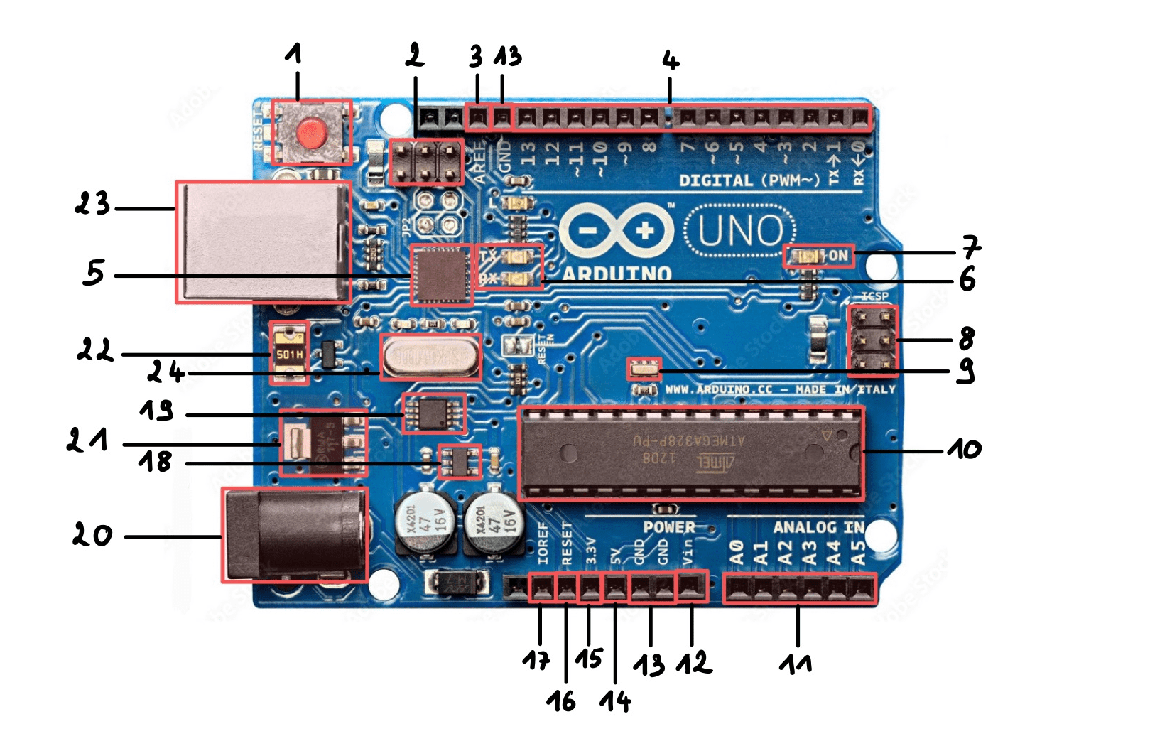
Arduino UNO’s Hardware
The schematics of the Arduino UNO board are easily accessible online on the official website. In this section, a description of most components is given.
Resetting the board
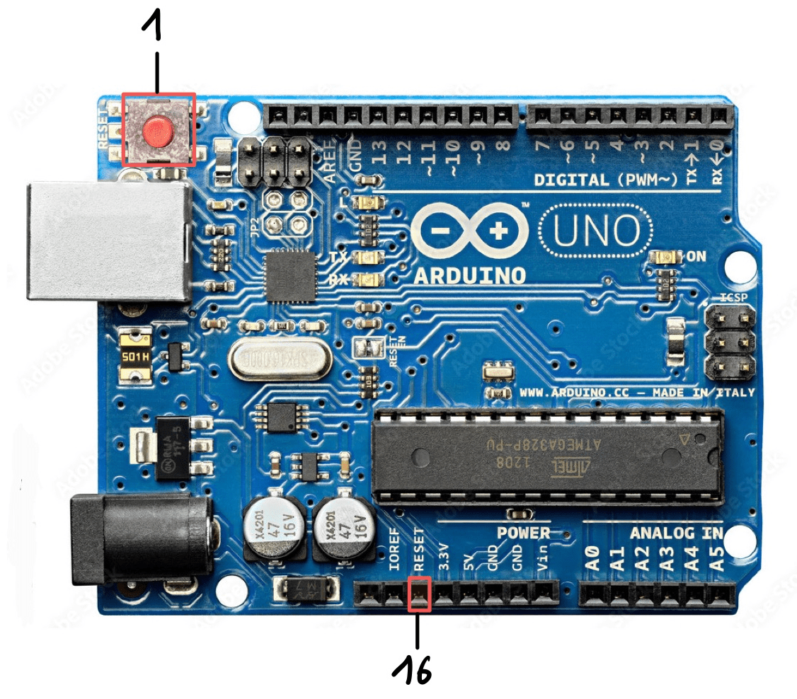
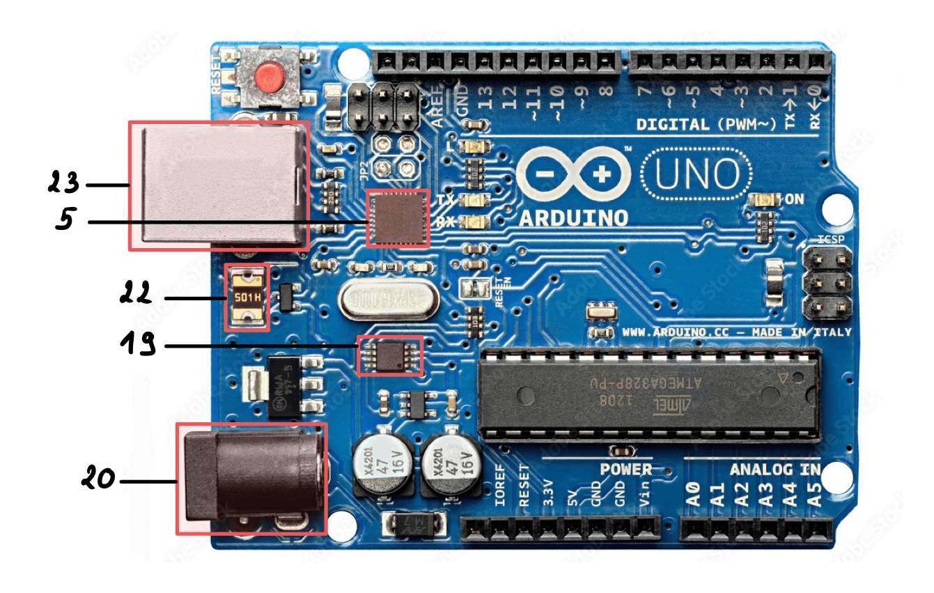
There are two ways to reset the ATmega328P microcontroller. The first one is through the Reset button (1). This button is connected to the reset pin of the microcontroller: when it is pressed, the pin is pulled to the ground and the chip will reset. The other way to reset is through the reset pin (16): it is for example possible to connect a button to it.
The pins
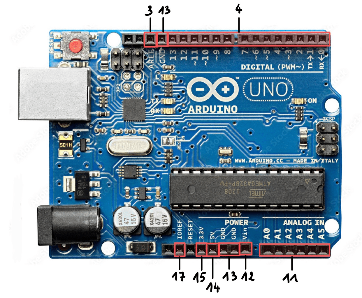
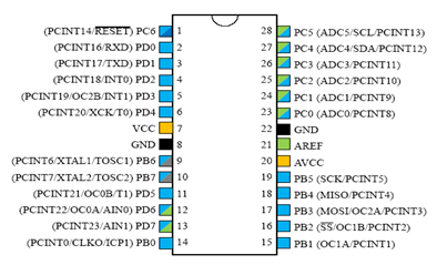
The Arduino UNO is equiped with various pins that each has a specific functionnality:
- Digital Input/Output Pins (4) → there are 14 of them (from D0 to D13), they are indicated on the circuit board with a
~. Six of these pins can provide a PWM output but can also be configured as inputs to read logical (0 or 1) or numerical values. This is the case of the D3, D5, D6, D9, D10 and D11 pins. - Analog Inputs Pins (11) → there are 6 of them (from A0 to A5). They allow to read an analogic signal from a sensor for example. To read the signal with the microcontroller, the Arduino board uses an analogic/numeric convertor called CAN convertor.
- Vin Pin (12) → useful to power the Arduino with an external power supply.
- GND Pins (13) → ground pins (0V). There are multiple such pins on the board.
- 5V Pin (14) → 5V power supply pin.
- 3.3V Pin (15) → 3.3V power supply pin.
- AREF (Analogic Reference) Pin (3) → is useful to define an external reference voltage (between 0 and 5V) as a limit for the input analog pins.
- IOREF Pin (17) → gives the reference voltage at which the board works. Useful when using Arduino shields.
ISCP
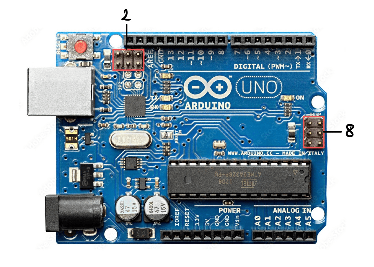
Before explaining what ISCP is, let’s first take a dive into what SPI is. SPI stands for Serial Peripherical Interface, it is a synchronous serial protocol used for communication between systems. It is commonly used by Arduino boards to do the communication between microcontrollers and sensors or other devices. It works with a system of master and slaves devices: the master can send data to the slave, the slave can at the same time send data to the master, but slaves cannot communicate with each other. There can be only one master with this protocol (the Arduino board in our case), however there can be various slaves (different sensors or peripherals for example).
SPI needs four dedicated pins:
- MOSI → Master Output Slave Input. It is used to tranfer data in both ways.
- MISO → Master Input Slave Output. It is also used to transfer data.
- SCK → Serial Clock. It is used to synchronize the data transmission.
- CS → Chip Select. It is used to determine whether the peripheral should communicate with the master or ignore the communication.
Now that we know what SPI is, let’s see what ISCP is. ISCP stands for In-Circuit Serial Programming and is also called ISP for In-System Programming. It is an AVR connector that has six pins (MOSI, MISO, SCK, RESET, VCC and GND). In a more general way, ISCP is used for data transfers for microcontroller programming (AVR for example), it actually uses SPI serial protocol for the data transfers. In the Arduino context, ISCP is used to program microcontrollers that are on the board, on a low level basis (bootloader, assembly…). On the Arduino UNO, there are two of them: one for the ATmega16U (2), the USB-TTL, and another one for the ATmega328P (8).
Each of the six pins used for ISCP have a specific functionnality:
- MOSI → Master Output Slave Input. It is used to tranfer data in both ways.
- MISO → Master Input Slave Output. It is also used to transfer data.
- SCK → Serial Clock. It is used to synchronize the data transmission.
- RESET → used to reset the microcontroller
- VCC → used to power the microcontroller.
- GND → ground pin (0V).
Leds
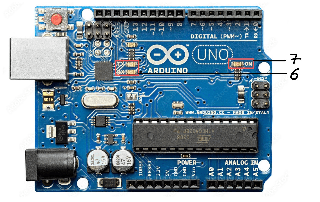
The Arduino UNO has integrated leds on its circuit, each of them has a specific role:
- RX led (6): indicates the reception. It blinks during the receiving process, depending on the speed of the data being received (in bauds).
- TX led (6): indicates the transmission of data. It blinks during the sending of serial data, depending on the speed of the data being transmitted (in bauds).
- Alimentation led (7): indicates whether or not the board is properly powered. It is turned on when the Arduino is plugged to a power supply.
Voltage regulators
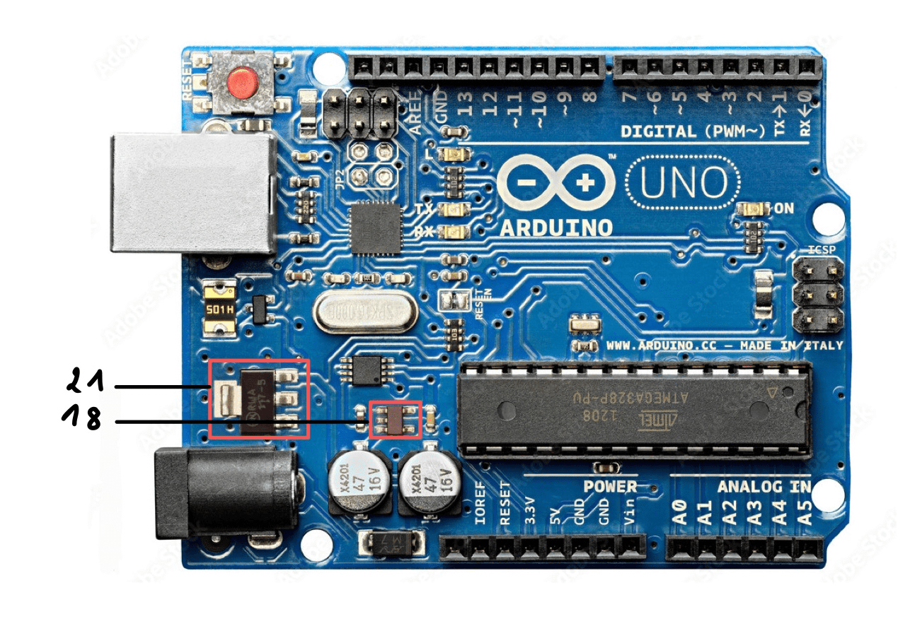
It also has two different voltage regulators: a 3.3V regulator (18) that is used to provide 3.3V through the 3.3V pin, and a 5V regulator (21) used to provide 5V to the microcontroller and the 5V pin. As indicated by its name, this component is responsible for maintaining a constant voltage.
Resonator and quartz oscillator
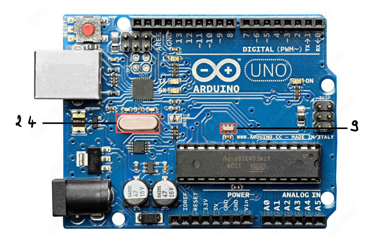
The circuit board is also equiped with a 16 MHz resonator and a 16MHz cristal oscillator. They both allow to implement timers or relative time. However, it is important to note that components giving absolute time, such as “Real Time Clocks” (RTC) are very different and quite expensive. On microcontrollers such as the ones used on Arduino board, it is quite unlikely to find them. However, it is possible to connect a RTC to an Arduino, as explained in this article: Accurate Clock Arduino UNO.
In our case, it is important to know that for a microcontroller to work, it needs a clock source, thus the presence of a resonator and a quartz oscillator. They allow to determine the speed at which the microcontroller they are linked to operates. The ATmega series microcontrollers can actually use two types of clocks. The first one is the internal RC oscillator that is built in the microcontroller, but it is limited by its maximal frequency and is not very accurate. The other option is to use an external clock source. It is this last option that is used in the Arduino UNO. The 16MHz cristal oscillator (24) operates for the ATmega16U chip and the 16MHz resonator (9) is for ATmega328P microcontroller.
Even though resonators and cristal oscillators have a similar use, they have some differences:
- In terms of frequency range: 10kHz to 100MHz for the cristal oscillator and 190kHZ to 50MHz for the resonator (it has no impact in our case).
- In the output: the cristal oscillator has a higher stability output than the resonator. The resonator is for example more sensitive to temperature for example.
- Tolerance and sensitivity: the cristal oscillator is more sensitive to shock and vibration than the resonator. Also, the cristal oscillator is more sensitive to ESD (Electrostatic discharge) while the resonator has a high ESD tolerance.
- In terms of material it is made of: the cristal oscillator is made of quartz which makes them difficult to manufacture, while resonators are made of Lead Zirconium Titanate (also known as PZT) and are easy to manufacture.
- Applications: resonators are used in situations in which the frequency stability is not important, while cristal oscillators can be found in everything that have any electrical components, they can even clock PWM signals. Resonators are usually good for low-speed serial port communication, while cristal oscillators have frequencies that can also support high-speed serial communications.
The ATmega328P
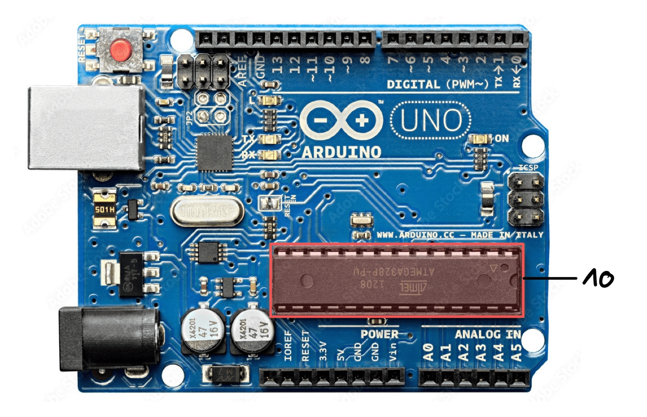
The ATmega328P microcontroller (10) is the “brain” of the Arduino. Here, it is pre-programmed with a specific bootloader that allows to directly upload the program through USB. The microcontroller is not soldered on the circuit board and thus, can be easily replaced if needed. Also, the pins of the Arduino UNO are the same as the ones on the ATmega328P. The Arduino environment makes it more easy to use and program.
Overall, the microcontroller is equiped with 14 digital input/output with some for PWM and others for analog, as shown in the image below.
Others
The Arduino UNO is also equiped with other components that allow the board to communicate with a computer or the preserve the microcontroller:
- USB-TTL Interface Chip (ATmega16U) (5): allows the board to communicate with the computer it is plugged on. In our case, the chip has custom firmware that makes it act as a USB-TTL interface.
- DC Barrel Jack (20): used to supply power to the board.
- LM358 (19): used as a comparator to control the input power path and protect the USB port. How it works: when power is provided through either the Vin pin or the DC Barrel Jack, it will cut off the USB power pin from the circuit, which will protect the USB port.
- Poly fuse (22): protects the integrity of the circuit board.
- USB connector (23): used for communication, to connect with a computer and load the firmware on the Arduino. It is also used to power the Arduino.
Arduino UNO and I2C
What is I2C?
I2C is a serial communication protocol used to transfer data between different devices, up to 128. It uses two lines to send and receive data: a serial clock (SCL) and a serial data (SDA). The SCL line is pulsed by the controller device at regular interval and data is sent through the SDA line. When on the rising edge of the clock pulse, a single bit of information is transfered from one device to another over the SDA line. It will then form a complete sequence with the other bits. For example: the adress of a specific device, a command or data.
With the I2C protocol, each device connected has its own adress. It is then possible to access just that adress, write or read from it, or just using other adresses if needed. What is interesting is that controller and peripheral devices take turn communicating over the SDA line. It is therefore possible for the controller to communicate with many other devices, with only two pins.
How to use it?
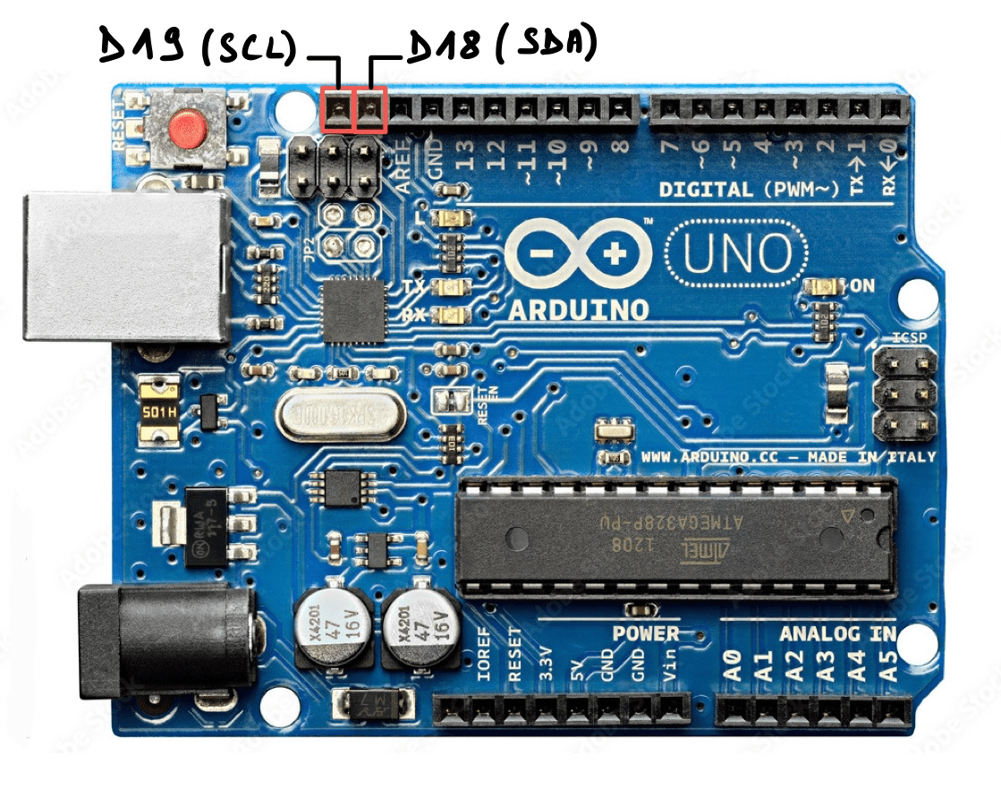
On the Arduino UNO, there are indeed an SCL and an SDA pin, they are D19 and D18.
It is for example possible to connect many different devices with this protocol: LCD, sensors, RTC…
To use it, the Wire library needs to be imported in the code with #include "Wire.h.
There are many tutorials available that shows how to use it, for example Arduino I2C Example.
Arduino UNO memory
Memory is essential for a microcontroller to work, it allows to store data temporarily or permanently, so that it can be used later. They are incorporated on circuit boards as memory blocks, which are semi-conductors devices that store and retrieve information. Then, the information is used by the microcontroller’s CPU to perform some specific tasks.
In our case, the Arduino UNO’s ATmega328P is in the AVR microcontroller family. There is also the ARM microcontroller family that exists and that is used in other types of Arduino boards (Arduino Boards Architectures).
Difference between volatile and non-volatile memory
Volatile memory is a temporary memory. In this case, data is stored while the system is running but is lost when the system is no longer on. Whereas non-volatile memory is a permanent memory: data persists in the memory blocks even when the system is turned off.
Different types of memory
Flash memory is a ROM (Read-Only Memory). This is where the system’s firmware is stored to be executed. For example, when we create a program on Arduino’s IDE, when we compile it, we then obtain a binary file that is stored in the flash memory of the Arduino board. The binary is then executed when the board is powered on. It is a non-volatile memory.
In microcontroller-based systems, RAM (Random Access Memory) is where run-time data as well as temporary data is stored. This is for example the case for the variables created by functions of a program. More precisely, RAM in microcontrollers is usually SRAM (Static Random Access Memory). It is a specific type of RAM that uses a flip-flop to store one bit of data and that retains data as long as power is being supplied. However, microcontrollers can also use another specific type of RAM: DRAM (Dynamic Random Access Memory), which requires one transistor and one capacitor to store one bit. It is also cheaper, but in turn, it consumes power which can be precious for small devices such as Arduino boards that may not have plenty of it. Hence, SRAM is very common for microcontrollers instead. In our case, the Arduino UNO uses SRAM. It is volatile memory.
EEPROM which stands for Electrically Erasable Programmable Read-Only Memory is, in microcontroller-based systems, also part of the ROM. More precisely, flash memory is actually a type of EEPROM. The difference between these two is how they are managed: EEPROM can be managed at the byte level whereas flash can be managed at the block level. In our case, both are used on the Arduino UNO. However, it is important to note that while EEPROM seems to be very practical, it is also more expensive and consumes more power compared to flash. EEPROM and ROM are non volatile memory.
Memory architecture in Arduino UNO
The Arduino UNO board uses a Harvard Architecture for its memory. But what is the Harvard Architecture ?
It is a kind of memory architecture that was first introduced in the mid 40s. It was named after the Harvard Mark I relay-based computer. Its main characteristic is that is uses two separate memory units: one for storing program instructions and another one for storing program data. These two memory units are accessed by the microcontroller’s CPU through different communication buses.
This type of architecture is more focused on performance as it is possible to have simultaneous access to instructions and data. It is therefore more suited for uses where an embedded processor must perform efficiently, reliably and at minimal cost. To be more precise, it is the ATmega328P on the Arduino UNO board that has a Harvard Architecture: programs are stored in flash memory and data is stored in SRAM. The major drawback of this architecture is that free data memory cannot be used to store instructions and that free instruction memory cannot be used by data.
Memory allocation
Memory allocation differs from one architecture to another (AVR or ARM for example). In our case, the Arduino UNO is AVR-based. Its SRAM is therefore organized into different sections:
- Text → contains instructions loaded into the flash memory
- Data → contains variables initialized in the sketch
- BSS → contains unitialized data
- Stack → contains data of functions and interrupts
- Heap → contains variables created during run time
Memory measurement and management
Arduino UNO boards don’t have a lot of memory available, it can therefore be interesting to know how much memory is left or to erase it. In our case, the board only has 2kO of SRAM, 32kO of flash and 1kO of EEPROM.
It is actually possible to check SRAM usage on Arduino boards with the following code from Michael P. Flaga’s library Arduino-MemoryFree:
|
|
For EEPROM, there is a native library that exist and that is already installed in the Arduino IDE. With it, we can easily, read, write or erase the content of EEPROM. Here is an example:
|
|
Conclusion
While Arduino UNO boards have been around for a few years already, they are still very popular and used widely. In this article, a general overview of Arduino UNO’s hardware was made, allowing to understand the role of each one of the components. Explanations of the I2C protocol, as well as how memory is organized on the board were also made. While the Arduino UNO can be used by beginners, it still has some interesting features that makes it complete for many projects: from educational ones to prototyping or more advanced ones.
Going further
On the Arduino UNO page, the schematics are available if you want to build an Arduino UNO from scratch or just have a look at the components and the circuit itself. Otherwise, some people have already made KICad schematics and BOM of the Arduino UNO which makes the building process a bit more simple.
Alternatives
Arduino UNO board is one of the most popular, but other interesting boards are out there. Here are some of them:
- STM32F3 Discovery
- SparkFun Thing Plus
- SparkFun RedBoard Artemis
- Esp32 DevKitC-VIE
- Arduino Nano
Bibliography
Arduino Documentation - Whats Arduino
Arduino Documentation - UNO rev3
Arduino Documentation - Memory Guide
Arduino Documentation - I2C Protocol
Arduino Documentation - Serial Protocols
Arduino Documentation - EEPROM Library
Learn Adafruit - Arduino Memory Architecture
Circuit Digest - Arduino UNO Board Hardware