Introduction
When watching an animated movie, or playing a video game, have you ever wondered how a computer manages to display such detailed 3D scenes on screen? How does a computer, which can only understand numbers, understand 3D shapes? How can it know where to place those shapes on your screen, and what colors they should be?
All of these questions can be answered by a key process used in computer graphics: the graphics pipeline. This process, which has been refined over decades (and still continues to evolve today) allows computers to manipulate 3D models, and convert them into pixels.
This article will serve as an introduction to the 3D graphics pipeline used by GPUs in personal computers, and will assume no previous knowledge on the topic from the reader. We will start by looking at how 3D objects are represented inside a computer, and then follow the stages that convert those objects into pixels. By the end, you will not only understand what the GPU does, but also why it is suited for this task.
How 3D objects are represented in computers
When you want to describe a 3D shape to your computer, you have to exclusively use numbers. The reason is that numbers are the only thing computers understand, so if we want a computer to work with 3D shapes, we need to find a way to describe those shapes using numbers too.
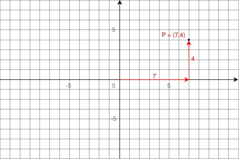
One way to do that is to express the shape as a collection of points placed in 3D space. To describe a position in 3D space, we can use a simple coordinate system, just like those in treasure maps: You can move left or right (horizontal axis), and up or down (vertical axis). A position in 2D is simply a combination of these axis.
Below are the coordinates of a point in 2D space. The point P is at 7 units to the right, and 4 units up. Its coordinates are then (7, 4).
 For 3D positions, we can just add another axis, for moving forward and backward.
By convention, these three axis are labeled X, Y and Z. With only three numbers
(one for each direction), we can then describe any position, for the points that
will form the basic outline of the shape. However, placing points is not enough:
We want to show surfaces.
For 3D positions, we can just add another axis, for moving forward and backward.
By convention, these three axis are labeled X, Y and Z. With only three numbers
(one for each direction), we can then describe any position, for the points that
will form the basic outline of the shape. However, placing points is not enough:
We want to show surfaces.
One way to form surfaces is to connect points to create polygons (flat 2D shapes made of straight lines). Think of triangles, squares, hexagons etc. They are all shapes that are flat. However, we are in a 3D world: When you connect more than 3 points, you are not guaranteed that the shape will lie on a single plane. Take a sheet of paper and think of the corners as points. Move only one of the corners and the paper will no longer be a flat surface.
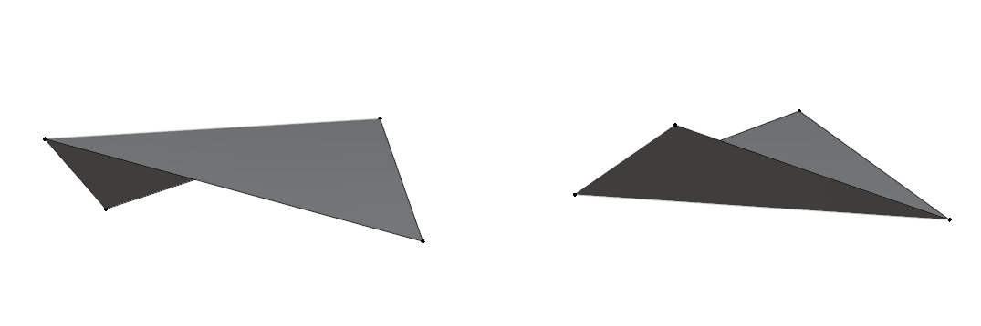 For that reason, triangles are the most suitable polygons to represent surfaces
in 3D. By being the simplest possible polygons, and always having their points
on the same plane, they are much easier and much reliable for a computer to work
with during rendering.
For that reason, triangles are the most suitable polygons to represent surfaces
in 3D. By being the simplest possible polygons, and always having their points
on the same plane, they are much easier and much reliable for a computer to work
with during rendering.
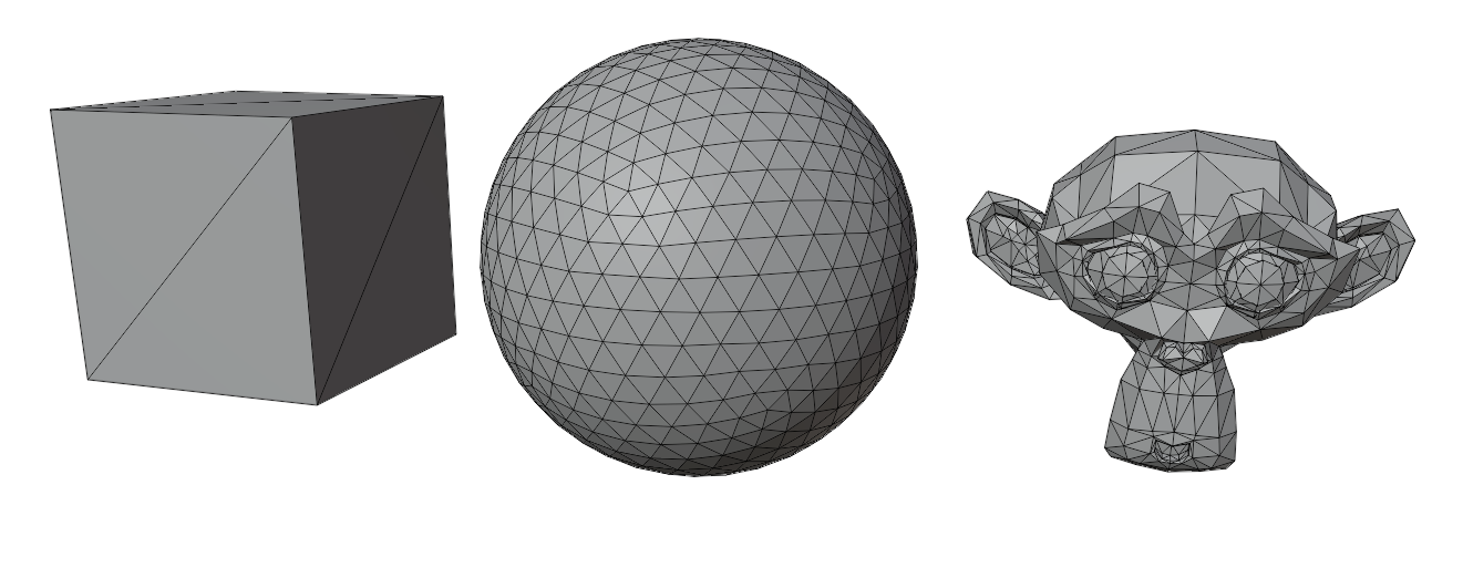
By connecting triangles together, we can then form the surface of any 3D shape.
 Position isn’t the only information you can attach to a point. While the
positions of the points tell the computer the outline of the shape, we can also
add extra information to help describe what the surface should look like.
For example:
Position isn’t the only information you can attach to a point. While the
positions of the points tell the computer the outline of the shape, we can also
add extra information to help describe what the surface should look like.
For example:
- Color: This information tells the computer what color the surface should be at that point.
- Texture coordinates: This tells the computer how to place an image on the surface.
- Normals: This information describes which way the surface is facing, thus helping with lighting and shading.
We’ve seen how we can describe points in 3D space, how to connect them into surfaces using triangles, and that we can attach extra information to these points. How do we actually store this inside a computer ?
The main idea is to have a list that will contain all the points, that we will now call vertices. Each vertex stores its position, and extra infomation like colors or normals. In the end, we just have a list of numbers, which is usually called the vertex buffer.
 For connecting the vertices, the most common way is to have another list that
tells the computer how to group the points into triangles. It does so by storing
numbers that refer to the vertices in the previously mentionned list. It is
usually called the index buffer.
For connecting the vertices, the most common way is to have another list that
tells the computer how to group the points into triangles. It does so by storing
numbers that refer to the vertices in the previously mentionned list. It is
usually called the index buffer.
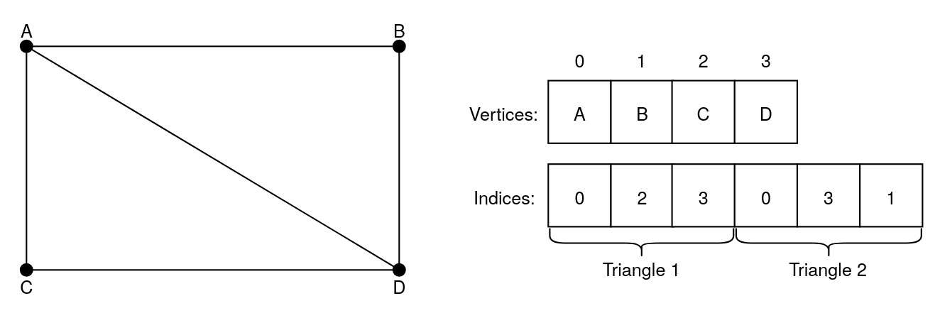 In this image, the first triangle is formed by connecting the points A, C and D,
and the second one is formed by connecting the points A, D and B. The two
triangles create a rectangle.
In this image, the first triangle is formed by connecting the points A, C and D,
and the second one is formed by connecting the points A, D and B. The two
triangles create a rectangle.
How does the GPU understand this data?
So far, we’ve seen how 3D objects can be broken down into lists of numbers. But how does your computer actually turn those numbers into pixels?
This is where a special component inside your computer comes in: the GPU, or Graphics Processing Unit. GPUs are pieces of hardware that are highly efficient at rendering. For that reason, we almost always rely on them for 3D rendering.
However, we can’t just give a GPU some lists of numbers. It wouldn’t know what to do with them. We need to give it instructions as well. To do that, we write programs that execute instructions on the GPU. These programs are called shaders, and they control specific parts of the rendering process.
Originally, shaders were only used to calculate shading, hence their names. However, as time went by, shaders began to do much more than that. Because turning 3D objects into pixels involves multiple steps, we can use different shaders for different parts of the process.
For this article, we will only focus on two types of shaders:
- Vertex shader: It is responsible for modifying the attributes of each vertex. For example, you can use it to move, rotate or scale the whole 3D object. It can even be used for creating more advanced effects, like making a surface ripple as if it were water, by moving the vertices up and down.
- Fragment shader: When the shape of the object is drawn, this shader is responsible for deciding what color each pixel should be. It can be used for applying textures on surfaces, adding lighting, creating glowing effects, and much more.
There are other types of shaders for more advanced graphics, but vertex and fragment shaders are the fondation of 3D rendering.
The graphics pipeline
At this point, we’re giving the GPU lists of numbers, and programs that tell it what to do with them. How does it turn all of that into an actual image ?
This is done by a conceptual model called the graphics pipeline.
The graphics pipeline is a step-by-step process that takes in the 3D data, and transforms it into the 2D image you finally see on your screen. Each stage of the pipeline takes care of a specific task, and passes its result to the next one. Some of the stages can be modified by a developper, through the use of shaders, which we covered in the previous section. However, others are fixed by the GPU itself.
In this article, we will only cover the key steps of the pipeline.
After getting the lists that represent the 3D object, here are the stages that transforms them into pixels:
Input assembler
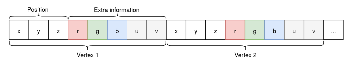
This is the first stage of the pipeline, and it takes in the vertex buffer. That list in itself doesn’t really make sense for the GPU, as it only is a long series of numbers, so when giving it to the GPU, we also have to specify the structure of a vertex. For example, let’s take a look at this list:
One vertex is exactly made of eight numbers. The first three numbers define the
position of the vertex. The next three are describing its color by combining
values of red, green and blue. The last two values are the texture coordinates
of the vertex.
Describing the structure of a vertex allows the Input assembler to break up the data into individual vertices and separate their attributes, preparing them for the next stage.
Vertex processing
This stage processes each vertex individually, running the vertex shader (which we covered in the previous section) on each one. Since this stage uses a shader that we can write, it is fully programmable, meaning we can customize what happens to the vertices.
The output of this stage is a new set of attributes for each vertex, which will be used for the next stage.
Primitive Assembly
After the vertices have been processed, they need to be grouped into “primitives”. In our case, we group them into triangles, using the index buffer we defined earlier.
Please note that it is also possible to not use an index buffer, and to just use the vertices in the order they appear in the vertex buffer. However, this means that if a vertex is used by multiple triangles, it would need to be duplicated, thus wasting memory in most cases.
At this stage, the GPU may also perform what is called culling. Culling is used to reduce the number of primitives that needs to be processed in the next stages.
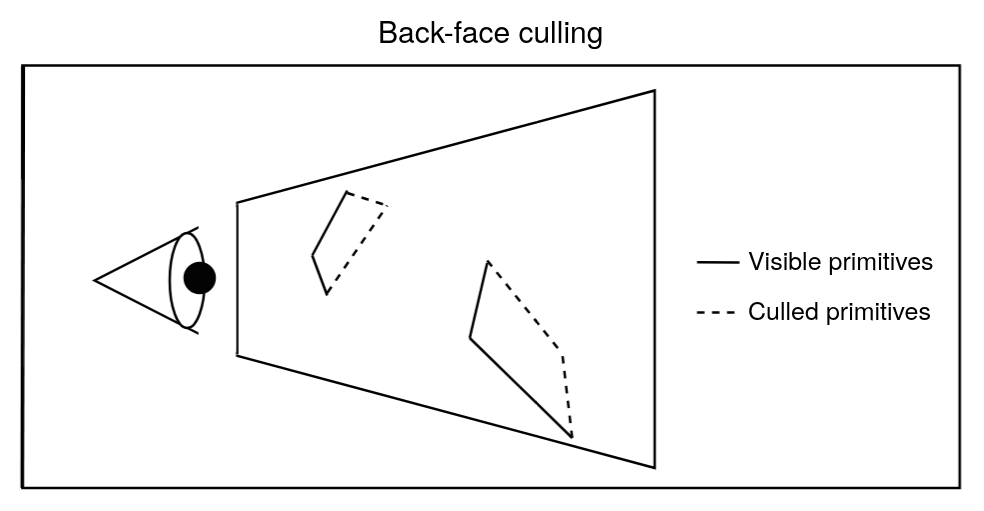 Here is a case of culling, where we discard primitives that are facing away from
the camera.
Here is a case of culling, where we discard primitives that are facing away from
the camera.
Finally, the triangles (primitives) are passed to the next stage.
Rasterization
For this stage, the GPU actually needs to draw the triangles it receives onto the screen. However, a screen is actually just a grid of tiny squares, which are called pixels. Each pixel displays a color, and by combining them, we get an image.
But triangles don’t fit into this grid of squares. The GPU needs to figure out which pixels are covered by which triangle. This process is called rasterization.
For every pixel that a triangle covers or touches, the GPU create a fragment. A fragment typically contains data such as the position of the pixel on the screen, how far the 3D point is from the camera (depth), and interpolated values of the vertex attributes (color, texture coordinates, etc).
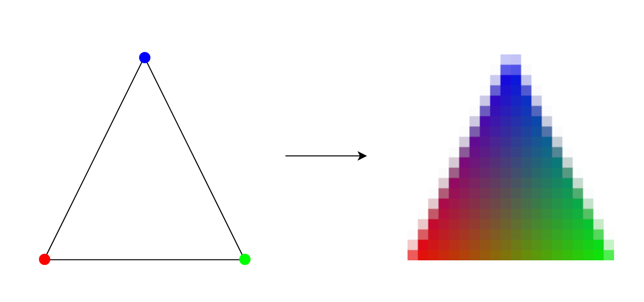 In the image above, you can see a triangle converted into fragments. Each
fragment corresponds to one pixel, and you can see how the color attribute is
interpolated across the fragments.
In the image above, you can see a triangle converted into fragments. Each
fragment corresponds to one pixel, and you can see how the color attribute is
interpolated across the fragments.
If multiple triangles overlap at the same pixel, the GPU generates just as much fragments for the pixel.
Every fragments are then sent to the next stage.
Fragment processing
As mentionned just above, this stage takes in every fragments individually. Its purpose is to process every information for each fragment, and determine the final color for the pixels that will be displayed on screen.
This is where the fragment shader, which was mentionned in the previous section, comes into play. Just like the vertex processing stage, this one is also fully programmable. This is where textures, lighting, shadings and more effects can be added.
This stage outputs a color for every fragment it receives.
However, the work isn’t done yet: the GPU now needs to decide whether the outputs of the fragment shader actually affects the final image. As said earlier, multiple fragments can map to the same pixel. The GPU needs to decide which fragments’ color are actually used in the final image.
Per-Sample/Pixel Operations
To resolve this, the GPU performs a series of steps to remove fragments that do not contribute to the final image. One of the most important is the depth test. This test checks how far each fragment is from the camera, and only keeps the ones closest to the viewer. This makes triangles in front hide the ones behind.
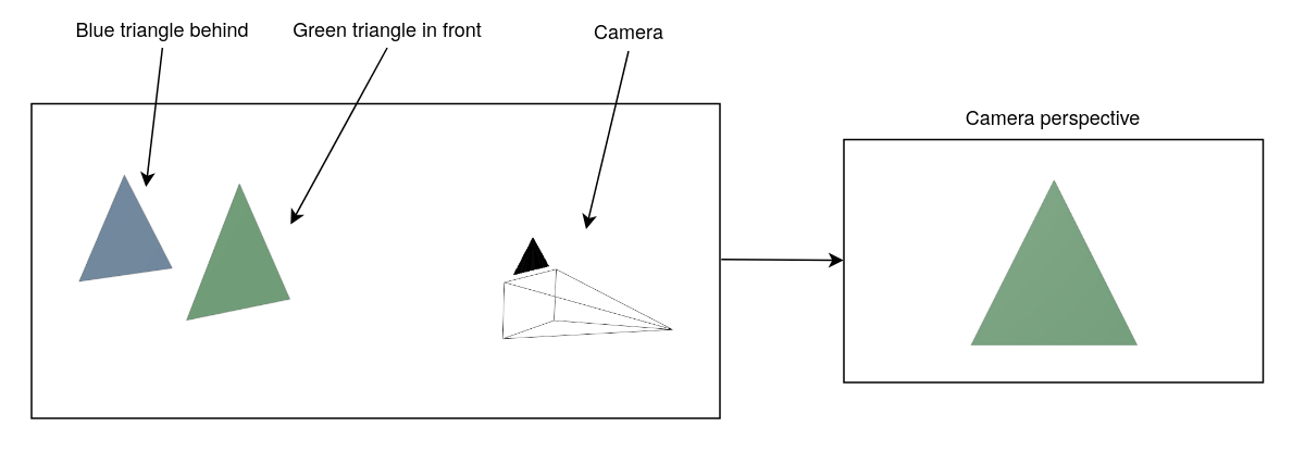 We won’t dwelve into all the details in this article, but the main idea is that
these tests only keep the relevant fragments.
We won’t dwelve into all the details in this article, but the main idea is that
these tests only keep the relevant fragments.
After the tests are completed, the GPU blends the colors of all remaining fragments mapped to the same pixel to determine its final color.
Why use a GPU for this?
As we have just seen, the graphics pipeline is a process that runs on the GPU. It involves processing a lot of data (vertices, fragments, pixels, etc) all at once. A GPU is built to handle this kind of task efficiently, but what makes it so suited for this ? To answer this question, let’s take a quick look at the architecture of a personal computer’s GPU.
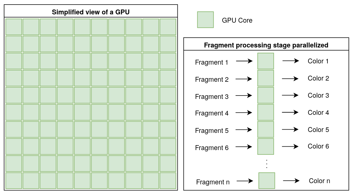
Inside it are many small cores. Each core can perform the same operation on different pieces of data at the same time. Their number ranges from the hundreds to the thousands.
For example, during the fragment processing stage, each core runs the same instructions (the fragment shader) on every fragments at the same time.
 This parallelism is what makes GPUs so well-suited for the graphics pipeline,
where the same calculations need to be repeated on many vertices, fragments,
etc, as we have seen in the previous section. Instead of waiting to process each
vertex or fragment one at a time, the GPU can handle large batches of data all
at once.
This parallelism is what makes GPUs so well-suited for the graphics pipeline,
where the same calculations need to be repeated on many vertices, fragments,
etc, as we have seen in the previous section. Instead of waiting to process each
vertex or fragment one at a time, the GPU can handle large batches of data all
at once.
Moreover, GPUs are optimized for mathematical operations needed for 3D rendering. These include matrix tranformations (which help move, rotate and scale 3D objects), as well as lighting and shading calculations.
In short, GPUs combine lots of small cores working in parallel, coupled with units designed for complex mathematical operations required for 3D rendering, making them especially suited for graphics rendering.
Conclusion
In this article, we explored how 3D objects are represented inside a computer, using vertices and triangles, and how they are converted into numbers. We then saw how those numbers are transformed step-by-step through the graphics pipeline to become pixels you see on a screen.
We also learned about shaders, which are small programs that run on the GPU that allow us to perform specific operations on the data we give them.
Finally, we saw why GPUs are suited for this job: their architecture, with hundreds to thousands of small cores working in parallel, allows them to process massive amounts of data, and perform complex math faster.
It’s important to note that the graphics pipeline covered in this article is mainly used for real-time rendering, which is what is used for video games or 3D applications where speed is essential.
There are other methods for rendering 3D objects, such as ray tracing or ray marching, which can produce more realistic images, but require more time and computing power.
I didn’t cover these methods in this article, but I think they are worth exploring if you are interested in 3D rendering. You will find some useful resources below if you want to learn more.
Bibliography
Polygonal models
Shaders
Graphics pipeline
- A trip through the Graphics Pipeline 2011
- Fundamentals of the Graphics Pipeline Architecture
- How Real Time Computer Graphics and Rasterization work