0. Before you start
The article is roughly split into two halves: a theoretical dive into DSP and pitch-shifting algorithms, followed by an explanation of an existing STM32-based implementation. It draws on these concepts throughout, so some familiarity with sampling, time vs. frequency domain, FFT, filters, C, pointers, circular buffers, and microcontrollers will help you get the most out of it.
1. What is a guitar pedal ?
Starting with the basics, for those new to the guitar world, a guitar pedal is an electronic device placed between the instrument and the amplifier that modifies the audio signal before it reaches the amp. Because a guitar player uses both his hands to play, it is generally activated with a foot switch. Pedals cover a wide range of functions such as distortion, wah-wah, delay or pitch-shifting, the subject of this article. Here are some examples of pedal effect:
- Wah-Wah: Cream - White Room
- Delay: The Fall of Troy - F.C.P.R.E.M.I.X.
- Distortion: Soothsayer - Buckethead
- Pitch-shift: no bass just a pitch-shifted guitar: The White Stripes - Seven Nation Army
- Combined effects: pitch-shift & distortion on the hook: TK from 凛として時雨 - unravel
2. What is the difference between an analog and digital pedal ?
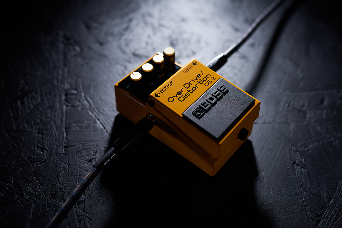
There are two types of guitar pedals, the most used is the analog pedal. Analog pedals process the signal as a continuous voltage, using discrete components (transistors, capacitors). The signal is never converted to numbers, it flows physically through the circuit, shaped by the electrical characteristics of each component.
Image 1: Boss - OS 2, overdrive/Distortion
The second type is digital pedals, they convert the analog audio signal into a stream of numerical values via an Analog-to-Digital Converter (ADC), process those values on a microcontroller or DSP, then convert the result back into an analog signal via a Digital-to-Analog Converter (DAC). This approach provides far greater algorithmic flexibility: the effect can be reprogrammed entirely without changing the circuit. Because this conversion and calculation take time, digital pedals must operate under strict real-time constraints. If the total round-trip latency (ADC -> DSP -> DAC) exceeds roughly 5 to 10 milliseconds, the musician will begin to feel a disconnect between their hands and what they hear. So it is important for a digital pedal to execute calculations nearly instantly and to preserve the immediate, organic response of an analog rig. The DMA (Direct Memory Access) is the bridge that allows the CPU to process samples without the overhead of manual data movement. The DMA controller autonomously transfers data between the $I^2S$ audio interface and the system memory
3. What is a pitch-shifter ?
A pitch-shifter is an effect that modifies the perceived pitch (fundamental frequency) of a sound without necessarily altering its duration. Unlike a simple speed change, which shifts both pitch and tempo simultaneously, a pitch-shifter aims to decouple these two parameters. In order to achieve that change in pitch, a digital pedal must first understand exactly what it is listening to. This process is called tracking, and it relies entirely on the pedal’s ability to lock onto the fundamental frequency. If a pedal cannot accurately identify the fundamental, the resulting sound will suffer from tracking lag, warbling, or harsh digital artifacts. There are two types of tracking:
- Monophonic Tracking: process only a single note at a time
- Polyphonic Tracking: process multiple notes at a time, allowing its use when playing full chords
Historically, the first analog pitch-shifters relied on variable-rate delay lines using Bucket-Brigade Devices (BBD): chains of capacitors that pass a sampled voltage from one to the next, read back at a different clock speed than it was written in.
It is conceptually identical to changing the Shift factor in the digital delay-line implementation covered later in this article, just done with clocked capacitors instead of a fractional read pointer in memory.
Since there is no sampling, no math, and no processor involved, BBD pitch-shifters are cheap and have near-zero latency, but their pitch range is narrow and sound quality degrades quickly with heavier shifts (noise, aliasing-like artifacts).
This is one of the main reasons the industry has almost entirely shifted to digital processing today, which is the focus of the rest of this article.
4. Theory Behind a Digital Pitch-Shifter
Now, let’s take a deeper dive into the theory behind a pitch-shift on a monophonic note. There are two ways to approach pitch-shifting: Overlap-Add (OLA) and Phase Vocoder
a. The Overlap-Add (OLA) Family
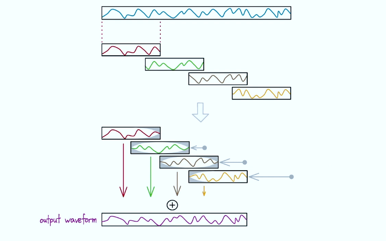
OLA is a family of time-domain algorithms that manipulate the waveform directly. Instead of changing the playback speed of an entire file, which alters both pitch and time together, they cut the audio into tiny blocks, rearrange their spacing in time, and blend them back together.
- Classic Overlap-Add (OLA): The incoming waveform is chopped into fixed intervals, overlapped, and summed into an output buffer. To pitch-shift, the individual blocks are resampled or played back at a faster/slower rate while the algorithm drops or duplicates blocks to maintain the original duration. The drawback of this simple approach is that OLA cuts audio regardless of where the wave cycle is. If two blocks are glued together mid-wave, it creates a phase mismatch. This manifests as an aggressive, metallic fluttering or sputtering sound. Furthermore, a sharp transient (like a drum hit or pick attack) can accidentally be copied into multiple blocks, causing it to echo or duplicate in time.
Image 2: OLA illustration (Credits: Geraint Luff - ADC22)
- Synchronized Overlap-Add (SOLA / WSOLA): To combat the fluttering, SOLA and Waveform Similarity OLA (WSOLA) introduce structural flexibility. Before summing an overlapping window into the output buffer, the algorithm uses a mathematical metric (like cross-correlation or measuring squared differences) to wiggle the block slightly left or right in time. It aligns the peaks and valleys of the waveforms perfectly before crossfading. This drastically reduces phase cancellation. These algorithms work wonderfully with monophonic tracks but struggle heavily with polyphonic chords.
b. The Phase Vocoder Family
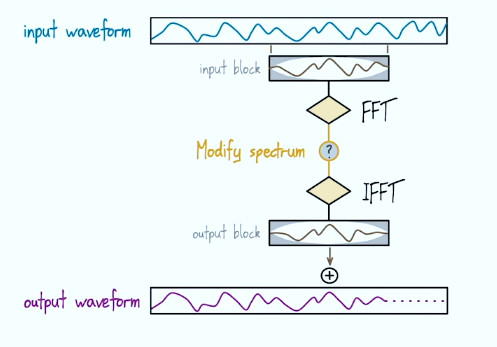
To handle polyphonic material, the pedal must process audio in the frequency domain. It chops the audio into small overlapped blocks, tapers the edges with a windowing function to eliminate edge discontinuities (in order to improve the FFT results), and applies a Fast Fourier Transform (FFT) to turn the wave into a spectrum of frequency bins (slices of frequency). The spectrum is modified, then an Inverse FFT rebuilds a playable audio signal.
Reminder: blocks are time related, bins are frequency related, so for example bin x of block n will transition over time to bin x of block n+1.
Image 3: Frequency-Domain illustration (Credits: Geraint Luff - ADC22)
-
The Standard Phase Vocoder: for every frequency bin, it tracks how the phase changes over time from block to block to estimate the exact frequency. It then shifts the spectral peaks to their new position, and recalculates the phase needed for a smooth transition. Because each bin runs this rotation independently, the system loses track of how frequencies line up with each other at any given instant. This creates parasitic artifacts (metallic swoosh, loss of punch, pre-echo) that soften transients like pick attacks.
-
Phase Vocoders with Transient Handling & Phase Resets: to fix this smearing, the pedal monitors energy spikes across bins. When a transient is detected, it forces a Phase Reset: every bin snaps its phase into perfect vertical alignment at that instant, restoring a tight, punchy attack at the cost of the smooth horizontal transition, traded back once the transient has passed.
c. The Hybrids Methods
The goal of this method is to smooth both the endless sustain and the sharp, punchy transients without resorting to a hard Phase Reset. The Hybrid Phase Method mathematically bridges the gap, allowing horizontal and vertical phase alignment to coexist smoothly.
-
The Hybrid Phase Method: A high-quality digital processor generates two simultaneous phase predictions for every point in the spectrum: a horizontal prediction (handling the smooth, singing sustain of the notes) and a vertical prediction (handling the immediate punch of the pick dynamics). The algorithm takes a weighted average of both predictions based on the local energy of the signal. If a note is sustaining solidly, the algorithm leans into the horizontal tonal phase, the moment a string is plucked, it seamlessly shifts weight to the vertical timing phase.
-
Hybrid Pitch and Time Stretcher: The algorithm scans ahead for sharp energy spikes, when an energy spike is detected, the engine passes that specific slice of time to WSOLA so the raw waveform stays perfectly intact. After the spike passes, it crossfade into The Phase Vocoder to handle the smooth sustain.
5. The implementation
The code I will explain is from YetAnotherElectronicsChannel, implementing a Delay-Line Pitch Shifter. Contrary to the algorithms we presented this one never chops the audio into separate windows or frame, instead it uses a single, continuous ring buffer. It smoothly slides a variable-speed playback pointer backward or forward through the buffer and crossfades between two running playback pointers to smooth the transitions. It is a much simpler implementation for educational purposes, it will work just fine for monophonic sound.
I also used Phil’s LAB’s DSP repository as a source. He created a repository about an electronic card for a digital pedal and implemented many pedal effects. Both recorded great youtube videos about these concepts that I more than encourage you to check (I will put a link to their youtube channels at the end of the article).
a. Hardware
| Features | STM32F405RGT6 | STM32F405VGT6 | STM32F407VGT6 |
|---|---|---|---|
| Physical Package | LQFP64 (Compact) | LQFP100 (Standard) | LQFP100 (Standard) |
| Pin Count (I/O) | 64 pins (51 I/O) | 100 pins (82 I/O) | 100 pins (82 I/O) |
| Memory (Flash / RAM) | 1 MB / 192 KB | 1 MB / 192 KB | 1 MB / 192 KB |
| TFT Screen Connection | SPI Only (Not enough pins for parallel) | SPI or FSMC (Parallel 8/16-bit) | SPI or FSMC (Parallel, cleaner pin multiplexing) |
| Code / DIY Ecosystem | Average (Requires code modification) | Average (Requires code modification) | Excellent (greatly used in open-source projects) |
| Estimated Price (Per Unit) | ~11.90 € | ~12.60 € | ~13.20 € |
| Feature | TLV320AIC3104IRHBR | PCM1808PW (ADC) + PCM5102APWR (DAC) Combo |
|---|---|---|
| Architecture | Single-Chip Audio Codec (Integrated ADC & DAC) | Discrete Split Chips (Separate Dedicated ADC and DAC) |
| STM32 Bus Pins Used | Low (Uses 1x I²S bus shared via DMA + 1x I2C for control) | High (Requires 2x separate I²S data lanes on the STM32) |
| Audio Resolution | 24-bit / up to 96 kHz | 24-bit / 96 kHz (ADC) | 32-bit / 384 kHz (DAC) |
| Hardware Configuration | Software-Controlled via I²S (Fully programmable registers) | Hardware-Controlled (Fixed via physical PCB pin strapping) |
| On-Chip Features | Integrated Programmable Gain Amplifiers (PGA), input mux, headphone driver | Bare-bones conversion. Requires external analog preamps and filters. |
| PCB Layout Complexity | Compact & Optimized (Single chip, shared analog/digital power planes) | Highly Complex (Requires routing separate analog/digital lines for two chips) |
| Total Solution Cost | ~4.90 € (Single Chip) | ~5.40 € (Combined: ~1.80 € for ADC + ~3.60 € for DAC) |
I will use an updated version of Phil’s Lab setup for easier future evolution: STM32F407VGT6, TLV320AIC3104IRHBR, and a TL072 input buffer.
Beware, the hardware is not the same as the implementation we will look at, so the drivers will need to be adapted (in this article we will only cover the pitch-shifter code).
b. Handling buffers
Real-time audio processing on the microcontroller is structurally managed using a double-buffering (ping-pong) DMA architecture to prevent audio discontinuities. While the I²S hardware fills one half of the memory with new samples, the processor is freed up to run the pitch-shifting algorithm on the other half.
However, the core algorithm inside the implementation by YetAnotherElectronicsChannel does not process data in static blocks or windowed frames like OLA or FFT methods do. Instead, it feeds the incoming samples into a single, continuous circular ring buffer, and reads it back through one fractional read pointer advancing at a different speed than the write pointer.
Buffer setup code:
|
|
c. The filter implementation
Beyond the core delay-line pitch-shifting logic, the implementation applies a high-pass filter to the incoming signal before it is written into the ring buffer.
This is a second-order Infinite Impulse Response (IIR) biquad filter1, cut off around 300 Hz at a 96 kHz sample rate, computed from five fixed coefficients and two delay lines carrying the previous input and output samples.
Applied upstream, this filter removes DC offset and low-frequency rumble introduced when the two stereo channels are summed, preventing that energy from being amplified by the pointer manipulation further down the chain.
High-pass Filter:
|
|
By changing the difference in speed between the writing and reading speed, the pitch change will happen:
- Pitch Shifting UP: The read pointer advances faster than the write pointer (e.g.
Shift = 1.4reads 1.4 samples per sample written), so the waveform is scanned faster than captured and the pitch rises. - Pitch Shifting DOWN: With a
Shiftfactor below 1.0, the read pointer creeps forward slower than the write pointer, effectively stretching the waveform and lowering the pitch.
To eliminate discontinuity artifacts at the boundary where the read and write pointers inevitably collide, the algorithm generates a second reading position by simply offsetting the same read pointer by half the buffer length (a 180° phase shift), rather than maintaining two independently moving pointers. The two read pointers will progressively cross-fade when the write pointer is less than 100 samples away from the current read pointer.
Pitch-shifting code:
|
|
6. Conclusion
This implementation serves as an ideal architectural starting point for a low-cost, real-time pitch-shifter pedal. It provides a direct, hands-on application of foundational digital signal processing concepts such as circular ring buffers, fractional dual-pointer readback, and time-domain crossfading, all working within an efficient embedded C framework.
Once the core hardware abstraction layer and I²S DMA streaming are stabilized, the natural software evolution path is clear: transitioning from this simple sample-by-sample delay line to a block-based WSOLA algorithm to accommodate complex polyphonic signals, and ultimately to an FFT-based Phase Vocoder if studio-grade, phase-coherent shifting is required. Scaling up to these heavy algorithms will significantly increase the CPU load. To maintain strict real-time constraints at 96 kHz without saturating the processor, it is strongly advised to optimize critical mathematical paths, such as replacing floating-point operations and rounding functions with fixed-point arithmetic or leveraging CMSIS-DSP optimized libraries.
The hardware platform is also versatile enough to support other DSP effects such as delays, reverbs, or distortions, with room to add a TFT interface for a fully customizable multi-effects pedal
7. Credits & Sources
YetAnotherElectronicsChannel’s github
YetAnotherElectronicsChannel’s youtube
YetAnotherElectronicsChannel’s STM32_DSP_PitchShift
YetAnotherElectronicsChannel’s STM32_DSP_PitchShift video
Four Ways To Write A Pitch-Shifter - Geraint Luff - ADC22
-
IIR is a second-order recursive biquadratic digital filter. In this configuration, it will heavily attenuate everything above 300Hz 96000 times per seconds:
$$y[n] = a_0 x[n] + a_1 x[n-1] + a_2 x[n-2] - b_1 y[n-1] - b_2 y[n-2]$$ ↩︎